Twisted-Pair Transmission of Closed-Circuit Video Made Easy
Introduction
With the pervasive adoption of twisted pair infrastructure for in-building communications, developers of closed-circuit television (CCTV) systems face increasing pressure to utilize this popular medium. Twisted-pair cabling (Category V, commonly known as CAT5, being the prevalent example) offers the end user many more signals per cable pulled and reduced termination costs compared to traditional coaxial-cable (coax) solutions.
The technical drawback to twisted-pair transmission, especially with commonly used unshielded-twisted-pair (UTP), is the tendency for common-mode noise pickup to degrade the video quality at the receive end amplifier. This receiver issue is effectively eliminated by using the LT6552 differential-input amplifier, due to the very high common-mode rejection-ratio (CMRR) of the part at high frequencies. The LT6552 also provides cable-driving output capability, thereby simplifying both the conversion of camera coax signals into twisted-pair transmissions and twisted-pair signals back to coaxial.
Twisted-Pair Video Line Receiver
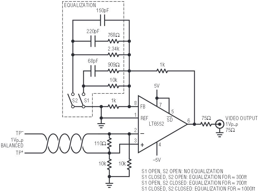
Figure 1 shows the LT6552 used as a combination twisted-pair line receiver, cable equalizer, and coax driver. The input wire pair is differentially terminated with 110Ω, and the output is back terminated with 75Ω. The circuit accepts 1VP–P differential input and delivers single-ended 1VP–P to a 75Ω display or video capture system input.

Figure 1. All-in-one twisted-pair video line receiver, cable equalizer, and display driver.
The nominal gain is 2.0, set by the 1kΩ feedback resistors, and this alone is satisfactory for short cable runs (up to 300ft). The additional RC networks provide three selectable loss equalizations (EQ) for use with various run lengths of CAT5. Slight under-equalization is not very noticeable on-screen, while over-equalization is rather apparent. One of the four selections will be acceptable for various cable runs up to about 1300ft. In stringent applications, an adjustable EQ circuit could be used instead of the fixed networks shown.
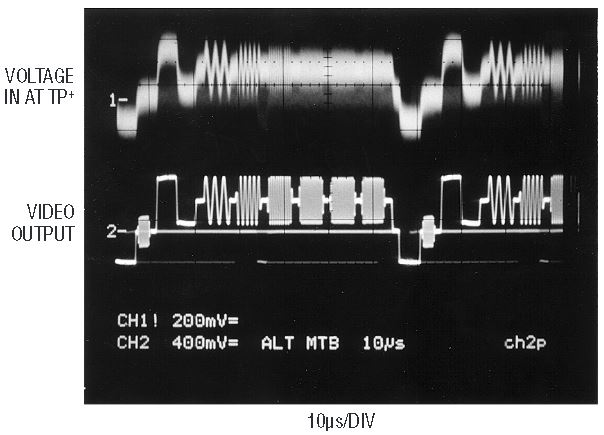
Figure 2 shows the response to a multiburst video test pattern, where the upper trace is the TP+ input after 1000ft of cable and the lower trace is the recovered output at the load, both with respect to local (receiver) ground. The LT6552 CMRR of ≥75dB across the video band (DC to 4MHz) completely eliminates the stray pickup evident in the upper trace, which includes AM radio signals (≈1MHz). The 1000ft equalization network accurately corrects the cable rolloff to produce a nearly perfect video response.

Figure 2. Multiburst video sent through 1000ft of CAT5 twisted-pair.
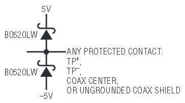
This circuit operates with supplies as low as 2.5V/–1.7V (assuming an AC-coupled video source), but ±5V is shown in order to maximize the available common-mode input range. The inputs are returned to ground through 10kΩ resistors so that appropriate circuit bias is assured during input disconnections. For extra ESD robustness, back-biased Schottky diodes may be tied to each I/O connection as shown in Figure 4.
Twisted-Pair Video Adapter/Line-Driver
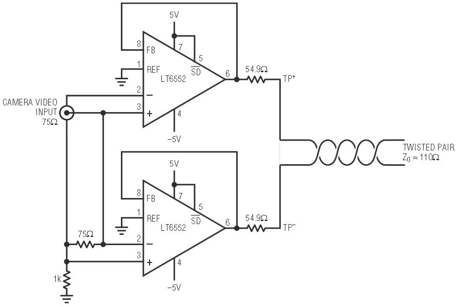
Figure 3 shows a pair of LT6552s connected as inverting and non-inverting unity-gain stages to form a balanced gain-of-two differential amplifier. The input cable is differentially terminated with 75Ω (as for camera video on coax), and the outputs are each back-terminated in half the characteristic impedance to form the twisted-pair line driver. The circuit accepts 1VP–P single-ended input and delivers 1VP–P differentially to a 110Ω load.

Figure 3. Super-simple coax to twisted-pair adapter.
Since the LT6552 inputs are fully differential, the coax shield could be left ungrounded, thereby eliminating ground-loop induced noise. The input cable shield is actually grounded through a relatively high impedance (1kΩ), which provides appropriate circuit bias during input disconnections but still prevents ground-loop noise.
As with the previous circuit, the exceptional CMRR of the LT6552 eliminates any stray pickup that the floating shield might have. The large differential common-mode range also permits significant ground-potential differences between the video source and the twisted-pair driver circuit, as is the case in many industrial settings. Here again, each I/O connection may be ruggedized as indicated in Figure 4.

Figure 4. Optional method for enhanced ESD protection.
Twisted-Pair Video Repeater
The circuits shown in Figures 1 and 3 could easily be coupled together at the coax connections to form a loss equalized repeater stage. This configuration offers additional 1000ft reach increments to a twisted pair run.
Conclusion
The LT6552’s exceptional CMRR makes it possible to transmit high-speed analog signals, like CCTV, over ubiquitous twisted pair cabling. In fact, a twisted-pair video transmission system is remarkably inexpensive, and easy to implement, using LT6552 building blocks and a minimal number of small external passive components.


