Telecom Hot-Swap Reference Design Is Immune to Overvoltage and Brownout Input Transients
Description
Introduction
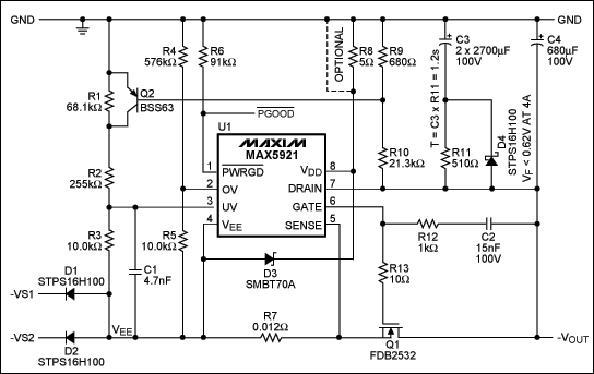
Telecom systems typically must provide full-power operation from either of two voltage sources that may range between -36V and -72V. Protection must additionally be provided against lightning-induced, higher-voltage pulses and occasional power brownout conditions where the input voltage may drop to 0V for several milliseconds. A plug-in line card may include a high-voltage to low-voltage DC-DC converter preceded by a hot-swap circuit. This circuit limits inrush current to little more than full-load current when the line card is hot-plugged into a live backplane. The hot-swap circuit must provide a power-good (active-low PGOOD) signal to activate the following DC-DC converter after on-card filter capacitors have reached full charge. A hot-swap circuit meeting all requirements is detailed in this document. Most requirements are similar to those of an AdvancedTCA® (ATCA®) first-level hot-swap circuit.
Typical Telecom System Requirements:
- Input Voltage: -43V to -72V Operation
- Two-Diode OR-ing at Input
- -32V to -36V Turn-Off (at the Power Source Before the Diode)
- 80W (max) Input Power, CLOAD = 680µF
- Withstand -150V, 1ms Overvoltage Pulse¹
- Ride-Through, 0V, 16ms Brownout Beginning at -43V Input Voltage; Active-Low PGOOD Must Remain Asserted Throughout this Period
- Inrush Current ≤ 1.5x Full-Load Current at 43V Startup Voltage
Reference Design Features and Considerations:
- The undervoltage-lockout (UVLO) increasing voltage is set to ~43V. The overvoltage-lockout (OVLO) increasing voltage is set to ≥ 72V.
- Two 100V Schottky diodes installed at the input allow OR-ing between two discrete sources.
- The UVLO decreasing voltage is set to ~32V. The design must satisfy Telecom System Requirement 6 while maintaining normal operation with active-low PGOOD active down to the UVLO decreasing voltage.
- PIN = 80W at VIN = 43V indicates an input current of 1.86A.
- A 70V TVS diode clamps any input-voltage pulse to a safe level for U1, C3, C4, and Q2. This diode may be placed either directly across the input terminals or across the VDD–VEE pins of the MAX5921 hot-swap controller and isolated from VIN with a 5Ω series resistor.
- An energy-storage capacitor (C3) stores sufficient energy to supply an 80W load for 16ms beginning at 43V and ending at 32V. This capacitor charges through a resistor to limit its charging current to a small percentage of the input surge current specified in Telecom System Requirement 7. A Schottky diode bypasses the charge-limiting resistor during discharge.
- A circuit-breaker minimum-limit trip point is selected to allow the 2.8A, 150% startup surge current at 43V and the 2.5A full-power operation down to 32V


