Synchronous Boost Converters Provide High Voltage without the Heat
Introduction
The LTC3813 and LTC3814-5 reduce the size of high voltage, high power boost converters by incorporating heat-saving features that eliminate the need for large components and heat sinks. In particular, two features significantly reduce heat losses over other high power boost solutions:
- Synchronous control eliminates the high power loss in the diode at high output currents
- Strong internal gate drivers reduce switching losses at high output voltages.
The LTC3813 can regulate output voltages up to 100V, while the LTC3814-5 is suitable for applications up to 60V. They both use a constant off-time peak current mode control architecture. Current mode control provides tight cycle-by-cycle monitoring of inductor current and constant off-time allows high conversion ratios such as 7V input to 100V output at 250kHz.
Advantage of Synchronous Control in High Power Boost Converters
As load current increases, synchronous boost converters have a significant advantage over non-synchronous boost converters due to the low power dissipation of the synchronous MOSFET compared to that of the boost diode in a non-synchronous converter. For example, an output load of 5A dissipates 5A • 0.5V = 2.5W in the diode in a non-synchronous converter. This high power dissipation requires a large package (e.g. D2PAK) and a heat sink, which adds complexity, cost and area to the power supply. In contrast, a synchronous converter using a typical 10mΩ MOSFET would dissipate only (5A)2 • 0.01Ω = 0.25W. Thus the synchronous MOSFET requires only a small SO8-size package and no heat sink to carry the same current.
Without heat sinking, the maximum load current of a non-synchronous boost converter is limited by the power dissipation of the boost diode. Assuming a thermal resistance of 50°C/W on the PC board where the boost diode is mounted, the DC forward current derating curves of atypical 5A Schottky diode show that at a 50°C ambient temperature, the maximum current the diode can carry is about 3A.
Feature-Rich Controllers
Besides synchronous conversion, the LTC3813 and LTC3814-5 provide many additional features for a high performance boost converter. No RSENSE™ current sensing utilizes the voltage drop across the bottom MOSFET to eliminate the need for a sense resistor—saving cost and simplifying board layout. For applications that require more accurate current limit, the LTC3813 can accommodate a sense resistor to achieve higher accuracy.
The off-time is programmable with an external resistor and, with an additional resistive divider from VIN to the VOFF, can be compensated for changes in input voltage to keep the frequency relatively constant over a wide supply range. Off-times as low as 100ns can be chosen to provide high VOUT/VIN step-up ratios. At low duty cycles, the step up ratio is limited by the 350ns minimum on time of the bottom MOSFET.
A high bandwidth error amplifier provides fast line and load transient response and a precise 0.8V, ±0.5% reference (0°C to 85°C) provides a very accurate output voltage. An internal undervoltage lockout comparator monitors the driver supply voltage and shuts down the drivers if the supply voltage is below a threshold that is safe for the power MOSFETs (6.2V for the LTC3813 and 4.2V for the LTC3814-5).The LTC3813 also provides a pin for undervoltage lockout on the input supply that is programmable with a resistive divider. Finally, the LTC3813 also has a phase-locked loop for external clock synchronization in noise sensitive applications.
A power good pin, accurate cycle-by-cycle inductor current limit, and overvoltage protection are additional fault protection features. Programmable soft-start ensures that the output capacitor ramps up in a controlled manner at start-up with no overshoot.
The LTC3814-5 provides a simplified feature set in a smaller more convenient package (thermally enhanced 16-lead TSSOP). The LTC3814-5 has a maximum output voltage of 60V and offers all the features of the LTC3813 except for input supply UVLO and external clock synchronization.
Strong Gate Drivers for High Efficiency
Because switching losses are proportional to the square of the output voltage, these losses can dominate in high output voltage applications with inadequate gate drive. The LTC3813 and 3814-5 have strong 1Ω gate drivers that minimize transition losses, even when multiple MOSFETs are used for high current applications. Dual N-channel synchronous drives combined with strong drivers result in very high power conversion efficiencies (see Figures 3 and 7). The LTC3813 uses a high voltage floating driver to drive the synchronous MOSFET at output voltages up to 100V (60V for the LTC3814-5).
The LTC3813 is optimized for driving 100V MOSFETs, which are typically rated at a VGS of 6V or higher. As a result, the LTC3813 has an internal under-voltage lockout that keeps the drivers off until the driver supply is greater than 6.2V, with 500mV of hysterisis. The LTC3814-5 is optimized for driving logic level MOSFETs, which are rated at a VGS of 4.5V and this version has an internal undervoltage lockout threshold of 4.2V with 500mV of hysterisis.
IC/Driver Supply Regulator
The LTC3813’s internal control circuitry and top and bottom MOSFET drivers operate from a supply voltage in the range of 6.2V to 14V(4.2V to 14V for the LTC3814-5). If the input supply voltage or another available supply falls within this voltage range it can be used to supply IC/driver power (see Figure 1a). If a supply in this range is not available, a single low current external MOSFET and resistor can be added to easily generate a regulated 10V (5.5V for the LTC3814-5) IC/driver supply using the internal linear regulator circuitry (Figure 1b). Using an external pass element has the advantage of reducing power dissipation on the IC and it also allows the transistor to be chosen with the appropriate BVDSS and power rating for the application—a small SOT23 package will often suffice.

Figure 1. Three ways to generate IC/driver supply.
Figure 1c shows a solution for applications that require the boost converter to continue operating when the input voltage has fallen below the undervoltage threshold of the IC. The cost is slightly lower efficiency. In this circuit, the regulator is connected to the output instead of the input. Diode D1 supplies power to the IC until the output voltage is high enough to generate the chip supply from the output. When the output is in regulation, the minimum input supply voltage is only limited by the maximum inductor current:

Since IC/Driver power loss is proportional to the output voltage in this circuit, it is only practical for output voltages of ~30V or less.
5V–14V to 24V, 100W DC/DC Converter
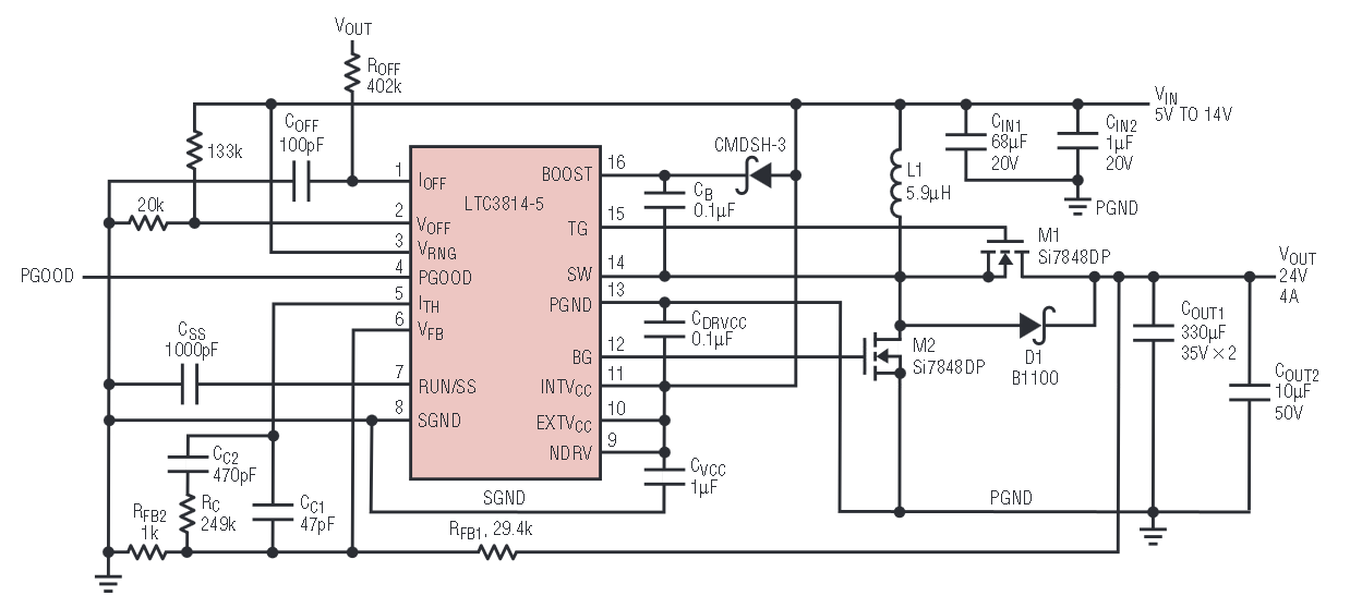
The circuit shown in Figure 2 generates a 24V output voltage at 4A from a 5V–14V input voltage using the LTC3814-5. Synchronous conversion allows the use of two small Si7848DP power MOSFETs and results in the high conversion efficiency shown in Figure 3. Since the input supply is within the LTC3814-5’s 4.2V–14V operating range, it can be connected directly to the IC supply pin. NDRV and EXTVCC are shorted to INTVCC to disable the INTVCC regulator.

Figure 2. 5V–14V to 24V, 100W DC/DC converter.

Figure 3. Efficiency of the circuit in Figure 2.
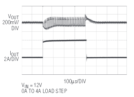
A 403kΩ resistor is connected from VOUT to the IOFF pin to set the frequency to 250kHz. Connecting the resistor to the output (as opposed to a constant supply voltage) has the advantage of keeping the frequency constant during output start-up. Connecting the resistive divider from VIN to the VOFF pin sets input supply range for constant frequency operation from 5V to 12V. The VRNG pin is connected to VIN to set the max sense voltage to 200mV. This sets the nominal peak inductor current limit to 200mV/0.01Ω = 20A using the Si7848DP MOSFET and, after accounting for parameter variations and inductor ripple amplitude, provides a maximum load of 2A at VIN = 5V and 4A at VIN = 12V. Figures 4 and 5 illustrate the outstanding load transient and overcurrent performance of the power supply.

Figure 4. Load transient performance of the circuit in Figure 2.

Figure 5. Overcurrent performance of the circuit in Figure 2.
12V–40V to 50V, 250W DC/DC Converter
The circuit shown in Figure 6 generates a 50V output voltage from a 12V–40V input using the LTC3813. Since the maximum input voltage is greater than 14V, the LTC3813 produces a regulated 10V from the input supply using a ZXMN10A07F MOSFET in a SOT23. A resistive divider is connected from VIN to the UVIN pin to set the undervoltage lockout threshold to 10V on the input supply. This ensures that the boost converter doesn’t hang at start-up when the powered by a current limited source supply when the output is drawing full load. Its efficiency is shown in Figure 7.

Figure 6. 12V–40V to 50V, 250W DC/DC converter.

Figure 7. Efficiency of the circuit in Figure 6.
Conclusion
The LTC3813 and LTC3814-5’s synchronous architecture and high voltage capability make them ideally suited for high voltage high power boost converters. They decrease complexity by eliminating the requirement for a large diode package and heat sink to dissipate its high power loss. Programmable frequency and current limit, wide output voltage range, and ability to drive logic-level or higher threshold MOSFETs provide maximum flexibility in using them for a variety of boost applications. Other features such as such as strong gate drivers to minimize transition losses, an accurate voltage reference, accurate cycle-by-cycle current limit, and an on-chip bias supply controller make the LTC3813 and LTC3814-5 the obvious choice for high performance, high power boost converters.


