Switched Capacitor Voltage Regulator Provides Current Gain
A switched capacitor voltage inverter is normally used to generate a negative supply voltage from a positive input supply. The negative supply current is equal in magnitude to the current drawn from the input. This design idea describes two circuits that use an inverter to double the current between the input and output, increasing efficiency and eliminating heat dissipation problems.
More Efficient than a Linear
If the roles of the ground and output pins are swapped (Figure 1), an inverter will divide the input voltage by two. This circuit can be used in place of a linear regulator when the input voltage is more than twice the desired output, for example, regulation of 12V to 5V or 3.3V.
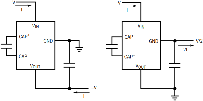
Figure 1. Rewiring a switched capacitor inverter for step-down regulation results in a current gain of 2.
The circuit’s operation is illustrated in Figure 2. An internal oscillator alternately closes and opens four switches. In the first half cycle, switches 1 and 2 are closed and current flows from the input to the output, charging C1. In the second half cycle, switches 3 and 4 are closed, discharging C1 into the output. The current delivered to the output is continuous and equal to twice the average input current. Because the output current is continuous, the output voltage ripple is low. Note that C1 and COUT do not need to be matched, as their voltages are equalized on each cycle.
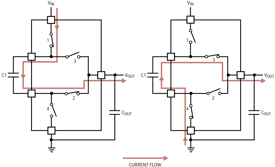
Figure 2. The LT1054’s internal switches alternately charge and discharge C1, delivering a continuous current to the output.
Figure 3 shows the actual circuit. Instead of halving the input voltage, the LT1054 modulates the input current (through switch 1 of Figure 2) to regulate the output voltage. This circuit can deliver 200mA at 5V from an input of 11.2V to 13V. Typical efficiency is 74%, compared to 42% for a linear regulator. More importantly, dissipation is decreased from 1.4W for the linear regulator to 0.35W, easily managed by the LT1054’s 8-pin surface mount package. For a 3.3V/200mA output, the circuit is 49% efficient, compared to a linear regulator’s 27%, with power dissipation reduced from 1.8W to 0.7W. A 6.2Ω resistor in series with C1 shares the dissipated power with the LT1054; no heat sink is needed.
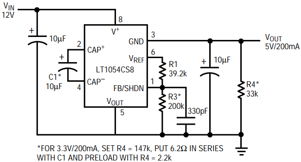
Figure 3. This switched capacitor regulator doubles the current between the input and the output, increasing efficiency and eliminating the need for a heat sink.
Three Diodes Improve the Inverter
The same advantages can be realized while generating a negative output. However, a switched capacitor inverter does not have the right compliment of switches. By adding three diodes (see Figure 4), the inverter can charge two capacitors in series and then discharge them in parallel to an output capacitor. The absolute value of the output voltage will equal half of the input voltage, minus some loss due to the switches and diodes.
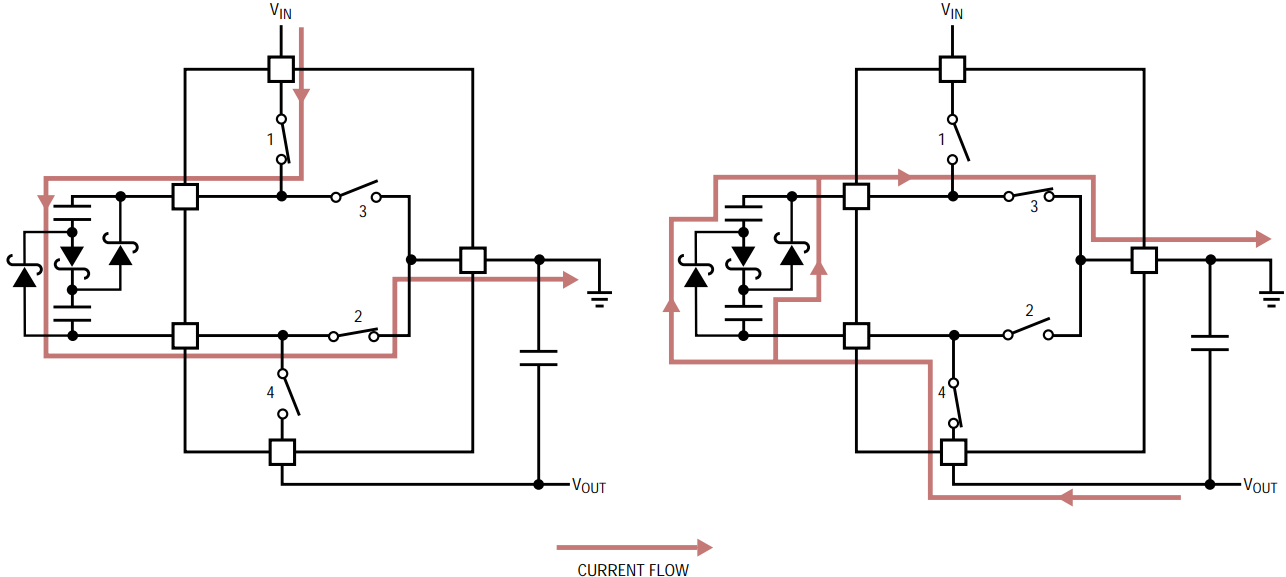
Figure 4. Adding three diodes to a switched capacitor inverter doubles the current between the input and the output.
Figure 5 shows a practical circuit, which converts 12V to –4V. The LT1054’s servo loop keeps the output regulated to –4V over an input range of 11V to 15V and a load current up to 100mA. (Unfortunately, there is too much voltage loss to regulate to –5V from a 12V source.) Note that many negative supplies will power loads that can pull the output above ground (op amp circuits in particular); Q1 prevents such a load from pulling U1’s VOUT pin above its ground pin.
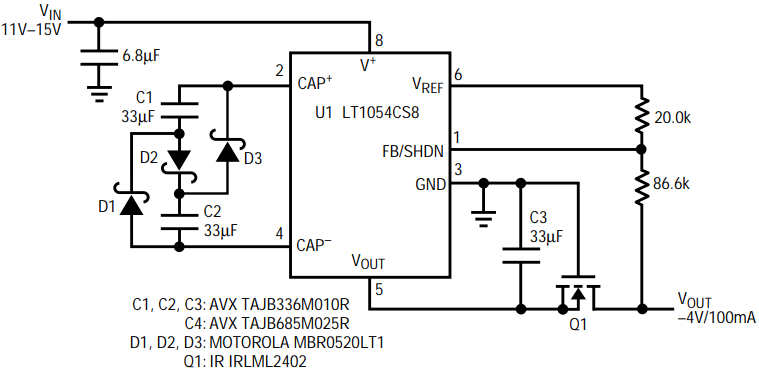
Figure 5. This circuit converts 12V to –4V. Only 63mA of input current is required for 100mA of output current.
Because most of U1’s operating current flows out of its ground pin, the input current to this circuit is a bit more than one-half of the output current. While delivering 100mA, the input from 12V was measured at 64mA, resulting in 53% efficiency. One alternative, a switched capacitor inverter followed by a linear regulator, would be 33% efficient at best and power dissipation would be 0.8W. This circuit dissipates only 0.35W, allowing this all–surface mount circuit to run cool.


