要約
The MAX1864 is a low-cost, multiple-output converter consisting of a switching buck circuit and two positive linear regulators. Although this IC's basic application circuit offers a low-cost, multiple-output supply, applications where lower noise is desired can benefit from this application note. This application note details the design and implementation of noise reduction for the MAX1864 auxiliary linear regulator.
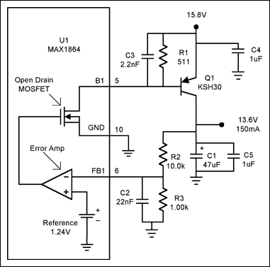
Figure 1. The basic MAX1864 auxiliary linear regulator
Figure 1 shows one of the two basic linear regulator circuits available in the MAX1864. In this circuit, an error amp followed by an open-drain MOSFET drives the external PNP transistor Q1. This, along with other external components, forms a linear regulator for up to 2A of output current at a maximum of 30V. Because there can be 200kHz switching activity from the main buck circuit, the high-gain linear regulator circuit can amplify the switching noise that shows up on the common ground plane. These noise spikes are amplified and sent to the output transistor where they are amplified even further. When these noise spikes conduct through the base of Q1, this transfers charge to the output capacitor. With no load, this can cause the output to rise above the output voltage set point. The switching noise is also seen on the output capacitor; larger output capacitors can reduce the noise, but adding capacitance might not be acceptable due to larger cost and board space.
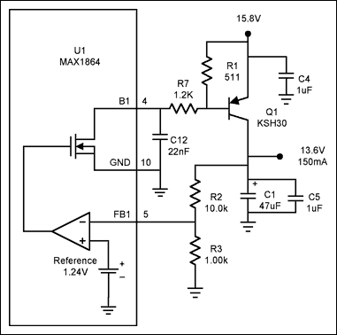
Figure 2. The addition of R7 and C12 provides switching noise reduction.
Figure 1 shows a capacitor C3 across Q1 base, this reduces noise that is amplified by the error amp. The rolloff frequency is quite high because of the low base impedance. In this case, with 0.150A emitter current the emitter resistance is:

With Re at 0.167Ω with a minimum Beta of 15, the worst-case impedance reflected at the base is 2.5Ω (Beta * Re). With C3 at 2.2nF, this filter begins to roll off at 29MHz. This is not an effective place for a filter to be applied because, at this point, the impedance is too low. The circuit in Figure 2 addresses this problem by placing a 1.2k resistor in series with the base of Q1 to raise the impedance. Then, with the addition of C12, a more cost-effective filter can be formed. Now, because the impedance seen by C12 is 1.2k, the rolloff (Frol) with a 22nF for C12 is:

Clearly, a 6kHz rolloff provides better filtering of 200kHz switching noise than the circuit in Figure 1. R7 must be selected so that it does not limit Q1 base drive current. This circuit, with R7 at 1.2k, can deliver a maximum of 12.6mA of base drive current to Q1. Power dissipation can also be an issue in R7. In this case, the maximum power in R7 is 200mW (1.2k * 12.6mA²). This assumes that there can be a maximum of 15.1V (15.8V - 0.7V) across R7. With a minimum Beta for Q1 of 15, the circuit can source a minimum of 190mA output current. In applications where lower output voltages are needed and the input voltage is lower, R7 will have to be reduced to allow the minimum base drive required for the specified output current. This might require a larger C12 capacitor to achieve the same filtering as in Figure 2.
To determine the frequency where C12 and R7 should roll off, the worst-case equivalent series resistance (ESR) for the output capacitor, C1, needs to be known. Then set the rolloff for R7/C12 to cancel the zero created by the ESR of the output capacitor. For example, if the lowest ESR of C1 is 0.6Ω, then this introduces a zero at:

Then, by setting Frol equal to Fzer, and if R7 has been selected at 1.2k, C12 can be found to be 22nF. In other words:

It is important to note that the circuit in Figure 1 also has a pole to cancel the ESR zero in the output cap. This pole is formed by the parallel combination of R2, R3, and capacitor C2. Unfortunately, this does little to filter the switching noise generated inside the chip. C12 in Figure 2 provides a dual-purpose role to both cancel the ESR zero, and filter internally generated noise at the chip output.
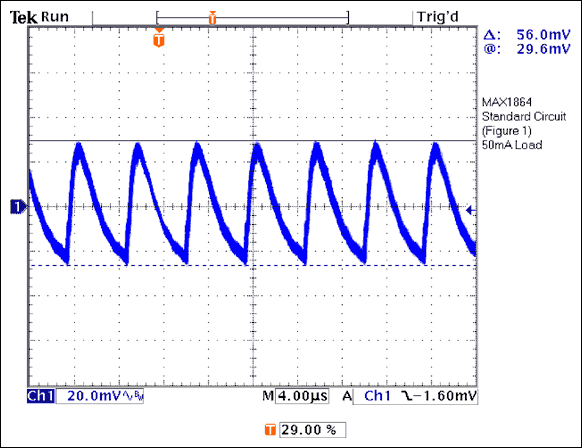
Figure 3. The noise pickup by the circuit in Figure 1.
Figure 3 shows the 200kHz noise that is generated when the switching buck is running and the circuit in Figure 1 is used. This output noise is very much dependent on the load on the switcher. From Figure 3 we can see that when the buck circuit generates noise, the linear output on C1 is driven up 56mV peak, then the load current of 50mA discharges the output. Figure 4 shows that placing a filter after the high-gain linear regulator circuit dramatically reduces the output noise to 7.3mV peak-to-peak. An added bonus is that less charge is injected through Q1, so full to no-load regulation is also greatly improved.
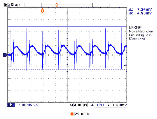
Figure 4. Under the same conditions as in Figure 3, the circuit in Figure 2 has a much lower output noise than the circuit in Figure 1.
The MAX1864 is a versatile integrated circuit that can provide cost-effective, multiple-output converters. A practical application circuit using the MAX1864 is shown in Figure 5. In this dual-output circuit, the buck regulator generates a 3.3V output at 7A, while the auxiliary regulator is generating a 5V output at 0.15A. Even with the loss generated by the drop of 7V on Q2, the overall efficiency for the circuit in Figure 5 is 89%.
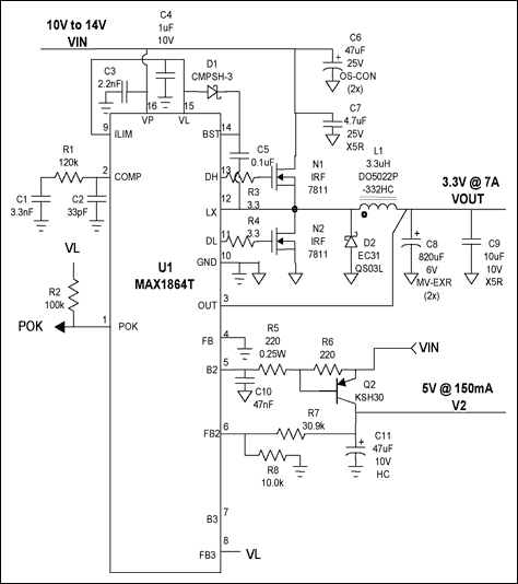
Figure 5. The MAX1864 dual-output circuit uses noise reduction.
| Vin |
Iin |
Vout |
Iout |
V2 |
I2 |
Efficiency (%) |
| 12.012 |
0.047 |
3.3220 |
0 |
5.0846 |
0 | — |
| 9.989 |
2.670 |
3.3262 |
7.007 |
5.0722 |
0.1505 |
0.902 |
| 12.008 |
2.259 |
3.3272 |
7.007 |
5.0743 |
0.1505 |
0.887 |
| 14.004 |
1.969 |
3.3276 |
7.007 |
5.0777 |
0.1505 |
0.873 |
Table 1 shows the tabulated data for this circuit. (Table 2 is a parts list.) It is important to note that this MAX1864 circuit has provisions for one more positive auxiliary regulator on pins 7 and 8. The MAX1865has extra positive and negative gain blocks in addition to the features of the MAX1864, providing the capability to generate quintuple-output power supplies. The MAX1964 and MAX1965 add the ability for power-up sequencing and tracking. The MAX8513and MAX8514 can also benefit from the noise-reduction techniques presented in this paper. The MAX1865, MAX1965, and MAX8514 all have negative output regulators and, although this is not presented here, the PNP transistor can be replaced with equivalent NPN transistors to facilitate the same noise-reduction techniques. These multiple-output supplies with reduced output noise are of much greater value to the engineer.
| Designation |
Quantity |
Description |
| C1 | 1 | 3.3nF ceramic capacitor (0805) |
| C2 | 1 | 33pF ceramic capacitor (0805) |
| C3 | 1 | 2.2nF ceramic capacitor (0805) |
| C4 | 1 | 1µF 10V X7R ceramic capacitor (0805) Taiyo Yuden LMK212BJ105MG |
| C5 | 1 | 0.1µF ceramic capacitor (0805) |
| C6 | 2 | 47µF 25V organic semiconductor cap Sanyo 25SC47M |
| C7 | 1 | 4.7µF 25V X5R ceramic capacitor (1210) Taiyo Yuden TMK325BJ475MN |
| C8 | 1 | 820µF 6V aluminum electrolytic cap Sanyo 6MV820EXR |
| C9 | 1 | 10µF 10V X5R ceramic capacitor (1210) Taiyo Yuden LMK325BJ106MN |
| C10 | 1 | 47nF ceramic capacitor (0805) |
| C11 | 1 | 47µF 10V aluminum electrolytic cap Sanyo 10MV47HC |
| D1 | 1 | 100mA 30V Schottky diode (SOT-23) Central Semi CMPSH-3 |
| D2 | 1 | 3A 30V Schottky diode Nihon EC31QS03L |
| L1 | 1 | 3.3µH 15A Power Inductor Coilcraft DO5022P-332HC |
| N1, N2 | 1 | 12mΩ N-channel MOSFET (SO-8) International Rectifier IRF7811 |
| Q2 | 1 | 1A 40V PNP transistor (D-PAK) Fairchild KSH30 |
| R1 | 1 | 120kΩ 5% resistor (0805) |
| R2 | 1 | 100kΩ 5% resistor (0805) |
| R3, R4 | 2 | 3.3Ω 5% resistor (0805) |
| R5 | 1 | 220Ω 0.25W 5% resistor (1210) |
| R6 | 1 | 220Ω 5% resistor (0805) |
| R7 | 1 | 30.9kΩ 1% resistor (0805) |
| R8 | 1 | 10.0kΩ 1% resistor (0805) |
| U1 | 1 | MAX1864TEEE (16-QSOP) |


