LTspiceの活用法 - サードパーティ製のモデルをインポートする
要約
本稿では、「LTspice®」にサードパーティ製のSPICEモデルをインポートする手順を説明します。具体的には、.MODELディレクティブを使用して記述されたモデルと.SUBCKTブロックを使用して記述されたモデルをインポートする方法を紹介します。それらの方法を採用すれば、他の技術者と回路図を共有する際、最大限の移植性(ポーティビリティ)を確保することができます。
はじめに
LTspiceは、アナログ・デバイセズが提供するSPICEベースのシミュレータです。これを使用すれば、回路図を作成し、そのシミュレーションを容易かつ迅速に実行できます。多くの場合、設計初期の段階では、理想的な回路素子を用いた簡素な回路図を作成し、シミュレーションによって基本的な機能や特性を確認します。但し、ある程度設計が進んだら、その簡素な回路図を基に、より現実的な部品のモデルを使用して改良を図っていく必要があります。
LTspiceには、コンポーネント製品の製造元(サードパーティ企業)が用意した数多くのモデルが付属しています(図1)。それらのモデルを使用するには、その部品のシンボルを右クリックして「Pick…」を選択します。すると「Select…」の形でデバイスの一覧が表示されるので、使用したい製品のモデルを選択してください。


必要なコンポーネント製品がLTspiceのライブラリに登録されていないケースもあるでしょう。そのような場合には、サードパーティ製のモデルをLTspiceにインポートして使用することができます。そのための手順は、デバイスの種類やモデルの形式によって異なります。
SPICEのモデルには2種類の形式があります。1つは、.MODELディレクティブによってその回路の振る舞い(機能や特性)を定義するタイプのものです。もう1つのモデルでは、.SUBCKTディレクティブによってその回路の振る舞いを定義します。本稿では、これら2種類のモデルをインポートする方法を紹介します。
以下で例にとる各サンプル・ファイルは、こちら からダウンロード可能な「ltspice-importing-third-party-models.zip」に含まれています。
【注意】
インポートするモデルのファイルが暗号化されている場合、そのモデルが.MODELディレクティブで定義されているのか、それとも.SUBCKTディレクティブで定義されているのかを判断するのが困難なことがあります。暗号化されたモデルに関するサポートが必要な場合には、モデルの提供元に問い合わせを行ってください。また、EngineerZone®のLTspiceフォーラムに質問を投稿すれば、そのコミュニティのメンバーが答えを提示してくれるかもしれません。
.MODELディレクティブのインポート
必要なデバイスのモデルが.MODELディレクティブによって定義されている場合、LTspiceにインポートするのは非常に容易です。.MODELディレクティブでは、デバイスの名前、デバイスの種類、そのモデルのパラメータの値が1行のコードとして記述されます。モデルによっては、以下のような非常に単純で理想化された記述になることがあります。
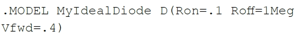
ただ、サードパーティ製のモデルの場合、現実のデバイスに即したより複雑なものになるはずです。典型的な例としては、以下のようなものが挙げられます。
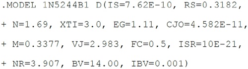
一見すると長いコードのように感じられますが、これも1行で記述されています。LTspiceにおいて、コード中の「+」はその行が前の行の続きであることを表します。
.MODELディレクティブの詳細や関連するモデル・パラメータについては、LTspiceのマニュアルにおいて、同ディレクティブに関するヘルプを参照してください。LTspiceのメニューから「Help」→「LTspice Help」を選択すると、LTspiceのマニュアルにアクセスできます。
.MODELディレクティブを回路図に直接組み込む
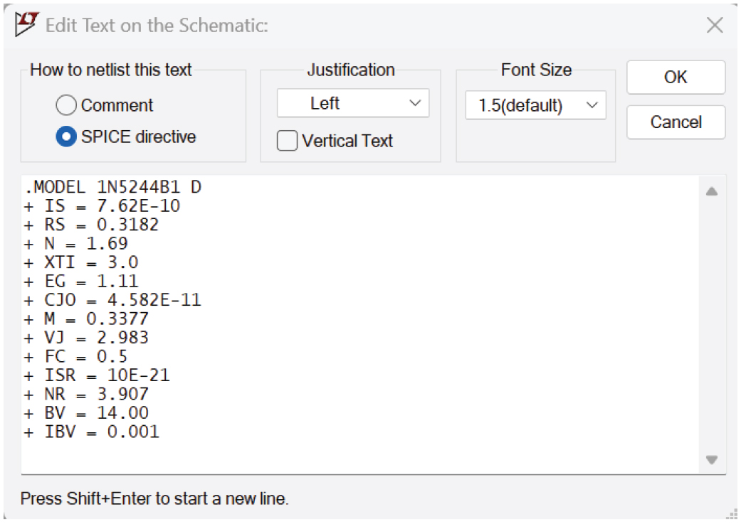
.MODELディレクティブをインポートするにはどうすればよいのでしょうか。1つの方法は、同ディレクティブを回路図の空き領域に直接記述するというものです。そのためには、メニューから「Edit」→「SPICE Directive」を選択します。あるいは、回路図上で「.」キーを押すことにより、「Edit Text on the Schematic」ダイアログ・ボックスを開きます。そして、入力フィールドに.MODELディレクティブのコードをコピー&ペーストし、「OK」ボタンをクリックしてください。その上で、回路図にテキストを配置します(図2)。

続いて、回路図にコンポーネントのシンボルを追加します。そして、そのシンボルが上記の.MODELディレクティブを参照するように設定します。ここでは、ツェナー・ダイオード「1N5244B1」を例にとっています。同ダイオードを配置するには、メニューから「Edit」→「Component」を選択し、表示されたリストから「zener」を選択してください。そして回路図の任意の位置をクリックし、ダイオードのシンボルを配置します。その際には、アナログ・デバイセズの製品のシンボルではなく、汎用のシンボルを選択してください。例えば、オペアンプのモデルをインポートする場合には、「AD822」ではなく「opamp2」などの汎用のシンボルを使用するといった具合です。
コンポーネントのシンボルと.MODELディレクティブをリンクさせるには、まずコンポーネントの値(フィールド)を右クリックします(図3)。コンポーネントを配置した初期の状態では、デフォルトの値として「D」というプレースホルダが表示されます。そこで、「Enter New Value」ダイアログ・ボックスにおいて、使用するモデルの名前を入力してください。この例では、「1N5244B1」と入力します。


この例についてより詳しく理解するには、前掲のzipファイルに含まれる「intrinsic_model_embedded.asc」をLTspiceで開き、回路図を参照してください。
テキスト・ファイルから.MODELディレクティブをインポートする
.MODELディレクティブの利用方法をもう1つ紹介します。それは、モデルの情報を記述したテキスト・ファイルを別途用意するというものです。モデルの情報を回路図とは別のファイルに保存すれば、回路図が煩雑になるのを防ぐことができます。特にモデルの情報が長大かつ複雑になる場合に有用です。
これについては、次のような方法で利用するのが最も簡単でしょう。まずはモデルについて記述したファイルを回路図のファイルと同じディレクトリに保存します。その上で、.LIBディレクティブを使用してファイルの内容を読み込みます。.LIBディレクティブを追加するには、メニューから「Edit」→「SPICE Directive」を選択します。あるいは、回路図上で「.」キーを押し、「Edit Text on the Schematic」のダイアログ・ボックスを開きます。モデルのファイルが回路図のファイルと同じディレクトリに保存されている場合、「. LI B [ファイル名]」と入力することでファイルを読み込めます。この例では、ファイル名として「1N5244B.txt」を指定します。
続いて、先述した方法によって、シンボルとモデル名をリンクさせてください。ここでは、モデルの名前を「1N5244B1」に設定します(図4)。


なお、ファイルの名前とファイル内に含まれるモデルの名前は一致しているとは限りません。また、1つのファイル内に複数の.MODELディレクティブが定義されている場合もあります。この点には注意が必要です。コンポーネントの値には、(ファイル名ではなく)必ずモデル名を指定してください。
この例の詳細については、zipファイルに含まれる「intrinsic_model_lib_file.asc」というファイルを参照してください。
.SUBCKTモデルのインポート
次に、.SUBCKT形式のモデルを回路図に組み込む方法を説明します。その方法は、.MODELディレクティブを組み込む場合と全く同じです。つまり、メニューから「Edit」→「SPICEDirective」を選択し、モデルの内容をテキストとして回路図にコピー&ペーストすればよいということです。あるいは、.LIBディレクティブを使用して、サブサーキットを定義したファイルの内容を回路図に読み込むことも可能です。
ただ、コンポーネントのシンボルを配置し、インポートした.SUBCKTのモデルとリンクさせる方法は、.MODELディレクティブをインポートする場合とは少し異なります。これについては、以下のセクションで詳しく説明します。
.SUBCKTモデルの使い方 - 既存のシンボルを再利用する
使用したい.SUBCKTモデルが、LTspiceのライブラリに既に登録されている標準的なシンボルと似通っているケースがあるでしょう。その場合、インポートした.SUBCKTモデルとそのシンボルを非常に簡単にリンクさせることができます。
ここでは、既存の回路図で使用しているNMOSデバイス「Si7884DP」を、インポートした「PSMN2R2-30YLC」(Nexperia製)のモデルで置き換える手順を詳しく説明します。そのモデルは、.SUBCKTを記述したファイル(PSMN2R2_30YLC.txt)として提供されています。その.SUBCKTの定義(.SUBCKTディレクティブの1文目)は以下のようになっています。

この定義において、「PSMN2R2-30YLC」はモデル名を表します。その後にはピン名(DRAIN、GATE、SOURCE)が続いています。このピン名の記述順は重要な意味を持ちます。これについては後ほど詳しく説明します。
PSMN2R2-30YLCはNMOSのデバイスです。そのため、LTspiceのライブラリに含まれているNMOSのシンボルをそのまま再利用できます。NMOSデバイスのシンボルを配置するには、「P」キーを押します(または「Edit」→「Component」を選択)。すると、各種デバイスのリストが表示されるので、その中から「nmos」を選択します。「Place」ボタンをクリックし、回路図上の任意の位置をクリックすると、そこにNMOSのシンボルが配置されます。
ここで、図5に示した回路図をご覧ください。図中のQ1はインポートされた.SUBCKTモデルを適切に参照しています。Q1の値に、モデル名である「PSMN2R2-30YLC」が設定されている点に注目してください。


以下に示す手順を再現するには、サンプル・ファイル「subckt_with_included_symbol.asc」を開いてください。これに含まれる回路図では、Q1はインポートしたPSMN2R2-30YCLのモデルを参照するようにあらかじめ設定されています。以下、Q2にも同じ.SUBCKTモデルを割り当てる手順を示します。そのためには、まず「Ctrl」キーを押しながらQ2を右クリックします。すると、「Component Attribute Editor」が開きます。このエディタで「Value」の値を「PSMN2R2-30YLC」に変更してください。つまり、.SUBCKTモデルの冒頭に記載されている名前を指定するということです。
重要な設定 - プレフィックスをXに変更する
次に、プレフィックスを「X」に変更します。これは、.MODELディレクティブをインポートする場合には不要だった手順です。既存のシンボルに.SUBCKTモデルをリンクさせる場合には非常に重要な意味を持ちます。


次に、LTspiceのライブラリに含まれるNMOSのシンボルのピン配置(記述順)がインポートしたモデルと一致していることを確認します。そのためには、「Component Attribute Editor」の「Open Symbol」ボタンをクリックしてください。すると、シンボル用のエディタが開きます。ここで「View」→「Pin Table」を選択すると、図7のようにピンの順番を示すリストが表示されます。それにより、DRAIN、GATE、SOURCEの順になっていることがわかります。これは、PSMN2R2-30YLCの.SUBCKTの定義におけるピンの記述順と一致しています。


.SUBCKTモデルの使い方 - 新たなシンボルを作成する
.SUBCKTモデルが既存のシンボルとうまくマッチしないケースもあるでしょう。その場合、LTspiceを使用すればそのサブサーキットに最適な新たなシンボルを自動生成することができます。ここでは、図8に示したサンプル・ファイル「LPF.cir」を例にとります。これは、簡単なRCフィルタの.SUBCKTモデルです。このファイルは前掲のzipファイルに含まれています。


まず、図9に示すように、.SUBCKT名の文字列(この例では「lowpass」)を右クリックします。続いて、メニューから「Create Symbol」を選択し、「保存」をクリックします。すると、シンボルのファイルが自動生成されます。このファイルは、必ずモデル・ファイルと同じディレクトリに保存してください。


図10に示したのが、自動生成されたシンボルです。この新たなシンボルは、シンボルのファイルを保存した際、LTspiceによって自動的に表示されます。


シンボルの属性からハードコードされたモデルのパスを削除する
LTspice上に表示されたシンボルを右クリックし、「Attributes」→「Edit Attributes」を選択します。シンボルの移植性を高めるために、属性「ModelFile」に設定されているパスの情報をすべて削除してください。削除できたら、「OK」ボタンをクリックし、シンボルのファイルを保存(「Save」のアイコンをクリック)してください。


新たに作成したシンボルの編集
新たなシンボルを追加できたところで、モデルの機能をより把握しやすくするためにシンボルのピンの位置を修正します。シンボルのピンの位置は、「Move」ツール(「M」キーを押す)を使用するか、メニューから「Edit」→「Move」を選択することにより簡単に調整できます。
新たなシンボルを回路図に配置する
シンボルのファイル(.asy)とそれに関連するサブサーキットのファイル(.cir)が、回路図のファイル(.asc)と同じディレクトリにあることを確認してください。新たなシンボルを回路図に配置するには、「P」キーを押すか、「Edit」→「Component」を選択し、「Component」ダイアログ・ボックスを開きます(図12)。続いて、「Show:」の部分にあるドロップダウン・メニューから「Schematic Directory…」を選 び、作成したシンボルを選択してください。「Place」ボタンをクリックし、回路図上の任意の位置をクリックすると、シンボルが配置されます。


回路図には必ず.SUBCKTモデルを記述してください。.LIBディレクティブを使用する方法、回路図に直接テキストとして記述する方法のうちどちらを使用しても構いません。図13は、回路図に.SUBCKTブロックを直接埋め込む方法を用いた場合の例です。


カスタムのシンボルやモデルを含むシミュレーション・ファイルの共有
作成した回路図を他の技術者と共有するにはどうすればよいのでしょうか。そのためには、回路図のファイル(.asc)、シンボルのファイル(. asy)、.LIBディレクティブで参照しているすべてのファイルを、同じディレクトリ内に保存します。その上でそのディレクトリの圧縮ファイル(ZIP形式)を生成してください。
まとめ
LTspiceには、あらかじめ数多くの実用的なデバイスのモデルが用意されています。ただ、サードパーティ製のモデルをインポートすれば、部品メーカーが提供する様々なモデルも柔軟に利用することが可能になります。本稿で説明した手順に従えば、そうしたモデルを使用した回路図を容易に作成できます。しかも、作成したデータは、他の技術者と簡単に共有することが可能です。
著者について
この記事に関して
製品カテゴリ
資料
設計ツール
シミュレーション・モデル
ソフトウェアおよびシミュレーション


