要約
A highly integrated solution, as seen with the MAX77860 USB Type-C 3A switch-mode charger, dramatically reduces system complexity by integrating the charger, the power path, the Safeout LDO, ADC, and the USB-C CC and BC 1.2 detection in a small 3.9mm x 4.0mm, 0.4mm pitch, WLP package. OTG functionality is seamlessly integrated without the need for an extra inductor. This level of integration simplifies the design, enabling the delivery of more power and more functionality in minimal PCB space.
Introduction
The new USB 3.1 Type-C™ standard is dramatically simplifying the way we interconnect and power our electronic gadgets. The standard utilizes the USB Type-C connector for data and power transfer between any two devices up to 100W. Accordingly, more functionality is required from the battery charging system, which tends to be increasingly smaller and lighter for every new portable device. This article reviews a typical USB Type-C charging system and shows how to simplify the design while delivering more power and more functionality in a smaller space.
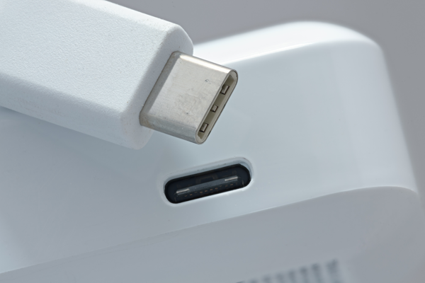
Figure 1. USB-C connector and smart phone.
USB 3.1 Type-C Standard
USB 3.1 Type-C (a.k.a. USB-C) is a new standard which supports high data rates and increased power delivery between electronic products. USB 3.1 can deliver 10Gbps of throughput while delivering up to 3A over standard cables and up to 5A over enhanced cables. The bus voltage can be adjusted up to 20V (60W at 3A with a standard cable or 100W at 5A with an enhanced cable). Many notebook computers today require less than 100W of power, hence new models adopting a Type-C connector can be charged via a USB port the way small devices are charged today.
The complexity of the USB 3.1 Type-C standard requires a device to negotiate as either a power provider (source) or power user (sink) before power transfer takes place. The connectors at both ends of a Type-C cable are identical, allowing for reversible plug-in. Each connector is also flippable, which allows it to be plugged in with either side facing up. Type-C USB also allows for bidirectional power, hence a peripheral device can be charged, and the same device can also charge a host device. This promises to eliminate many proprietary power adapters and many types of USB cables, ultimately reducing the maze of wires surrounding today’s desktops.
Configuration Channel Detection
A new feature of USB Type-C is configuration channel (CC) detection. The configuration channel logic detects cable presence, orientation, and current-carrying capability. Cable detection occurs when one of the two CC lines is pulled down. Which line is pulled down (CC1 vs. CC2) determines the cable orientation. The current-carrying capability is determined by the values of the termination resistors. Another new feature of USB Type-C is cold-plugging, namely the 5V is provided only after successful end-to-end detection is completed. This feature makes CC detection mandatory in USB Type-C applications.
USB 3.1 Type-C Typical System
Figure 2 illustrates a typical portable power management frontend equipped to connect to a USB Type-C cable and powered by a lithium-ion (Li+) battery.
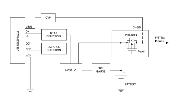
Figure 2. USB 3.1 type-C typical power management system.
When the VBUS voltage is present it powers the charger, the system, and the rest of the blocks. In this phase, the battery is charged via QBATT operating as a current source. When the VBUS is disconnected, the battery powers the system via QBATT operating as a “on” switch.
With the USB Type-C protocol, the CC1 and CC2 pins (Figure 2) determine port connection, cable orientation, role detection, and port control. The charger in Figure 2 also supports the legacy protocol Battery Charger 1.2 (BC1.2).
Typical Solution
The typical implementation of a battery system can be very costly in terms of BOM and PCB space. Figure 3 shows the PCB size of the charger and detection section implemented with two ICs, one for the charger and one for the two detection blocks in Figure 2. The two-chip solution plus passives occupies 61mm2.
2)." src="/jp/_/media/analog/en/landing-pages/technical-articles/how-to-shrink-your-usb-typec-battery-charger/6949fig03.png?rev=7b3834e6c7624e0596ec02d53b7db35d" class="img-responsive">
Figure 3. Common integrated solution PCB size (61mm2).
Highly Integrated Solution
Greater simplification of the BOM is achieved with a higher level of integration. In Figure 4, the blue highlighted box shows all the blocks that ideally can be integrated in a single power management IC (PMIC).
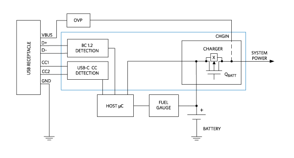
Figure 4. USB 3.1 type-c integration path.
With this level of integration, the system’s complexity is greatly reduced as shown in Figure 5.
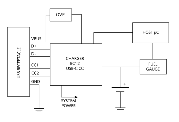
Figure 5. Integrated charging system.
Integrated USB Type-C Charger
A higher level of integration is seen in the MAX77860, a high performance, single-input switch-mode charger, which features USB Type-C CC detection capability (Figure 6) for single-cell Li+ batteries. The IC supports up to 15W applications and includes reverse-boost capability, a high-voltage LDO, and a 6-channel ADC. The switching charger is designed with a robust CC, CV, and die temperature regulation algorithm and input power regulation, as well as I2C programmable settings to accommodate a wide range of battery sizes and system loads. It fits inside a compact 3.9mm x 4.0mm WLP package.
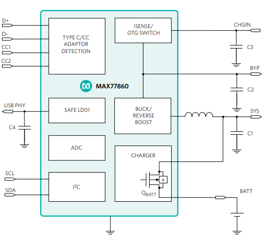
Figure 6. Integrated charger PMIC.
The corresponding PCB layout is shown in Figure 7. The integrated solution plus passives occupies only 42mm2, a 30% reduction in PCB size.
2)." src="/jp/_/media/analog/en/landing-pages/technical-articles/how-to-shrink-your-usb-typec-battery-charger/6949fig07.png?rev=0be7787b36674cedbc793a978bdb51ca" class="img-responsive">
Figure 7. Highly integrated solution with smaller PCB size (42mm2).
Ease of Use
In a typical system, the microcontroller or a host microprocessor configures the charger’s input current limit based on the current level that the port controller IC detects. The MAX77860 independently sets the charger’s input current limit, allowing the charger to charge the battery at the source’s full capability, which results in faster charging. This also simplifies host software development.
Design Flexibility
Backwards compatibility supports designs that work with both USB Type-C and legacy adapters. An integrated ADC frees up resources in the microcontroller, while providing accurate voltage, current, and temperature measurements for sophisticated power management.
Reverse-Boost for OTG Power
USB On-The-Go (OTG) is a specification that allows USB devices such as handheld computers and terminals, portable game players, and battery-powered health monitoring devices to act as a host. This allows other USB devices or accessories such as USB flash drives, digital cameras, mice, or keyboards, to be attached to them. The USB Type-C specification also allows a device to power other devices with the reverse-boost feature.
In charge mode, with S1 on, the switching regulator (S2 and S3 synchronous switching in step-down mode) bucks down the CHGIN voltage to the SYS pin. From there, the linear regulator, which controls the pass transistor S4, charges the battery (S4on).
In reverse-boost mode (OTG) with no input power, the battery voltage (S4 full on) is boosted (S2 and S3 synchronous switching in step-up mode) at the CHGIN pin (S1 on).
In this implementation, reverse-boost mode requires no additional inductor. The boosted CHGIN voltage is then used for the USB OTG function.
In battery-only mode, the switch S1 is off.
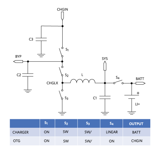
Figure 8. Charger and reverse-boost modes of operation.
Safeout LDO
The safeout LDO is a protected high-voltage input linear regulator that provides a programmable output voltage of 3.3V/4.85V/4.9V/4.95V via an I2C register. It is used to supply low-voltage-rated USB systems. The safeout linear regulator turns on when CHGIN = 3.2V and is disabled when CHGIN is greater than the overvoltage threshold.
Conclusion
The new USB 3.1 Type-C standard requires more functionality from battery charging systems, even while housed in portable devices that tend to be increasingly smaller and lighter. We reviewed a typical charging solution with its low level of integration, leading to large BOM that requires a big PCB area. A highly integrated solution, as seen with the MAX77860 USB Type-C 3A switch-mode charger, dramatically reduces system complexity by integrating the charger, the power path, the Safeout LDO, ADC, and the USB-C CC and BC 1.2 detection in a small 3.9mm x 4.0mm, 0.4mm pitch, WLP package. OTG functionality is seamlessly integrated without the need for an extra inductor. This level of integration simplifies the design, enabling the delivery of more power and more functionality in minimal PCB space.
Glossary
BOM: Bill of materials
CC: Configuration channel (Detection)
CC: Constant current (Charging)
CV: Constant voltage
OTG: On-the-go
Learn More
Overview of USB Battery Charging Revision 1.2 and the Important Role of Adapter Emulators
Choose the Right Buck Converter for Your USB 3.1 Type C Powered Devices


