How to Achieve Greater Accuracy in Battery Capacity Readings for Portable Designs
How to Achieve Greater Accuracy in Battery Capacity Readings for Portable Designs
2018年04月16日
要約
Because a product’s runtime is limited by battery capacity, it’s critical to have a precise method for measuring the remaining battery capacity to avoid an unexpected shutdown. This application note describes an experiment for obtaining accurate battery capacity readings in a dog-tracking project.
Introduction
My dog Mocha (Figure 1) often likes to run ahead of me during hikes for some off-trail exploring. She always finds me later, but sometimes long after I start looking for her, so I wanted to find a way to track her location easily. Looking through the Adafruit® website, I came across an interesting project. Adafruit is a New York-based open source hardware company that also offers a number of resources for people who want to experiment with or learn more about electronics. The company’s GPS Logging Dog Harness project involves using Adafruit’s sewable microcontroller platform called FLORA® and a GPS module to track a dog’s location. I thought this would be a great way to monitor my dog’s activity on our hikes, so I took on the wearable dog-tracking system project with my colleague Mohamed Ismail.
 Figure 1. Mocha, the author’s dog, ready for a hike.
For our prototype, in addition to FLORA and the GPS module, we incorporated a MAX1472 ISM transmitter to broadcast the GPS coordinates, as well as four FLORA RGB Smart NeoPixel® LEDs to make Mocha more visible during night hikes. These NeoPixels also served to indicate the remaining charge in the battery so we would know when to get my leash, before the system shuts down. We used green to represent a charge of 50% or more, yellow to represent a charge between 50% and 25%, and red to represent a charge of 25% or less. Figure 2 shows our original design.
 Figure 2. Wearable dog tracker system.
In our original iteration, nearly everything worked perfectly—we were able to get GPS coordinates, flash the different NeoPixel colors, and broadcast coordinates with the ISM transmitter. Our method for monitoring the battery’s state of charge (SOC), however, did not work as expected. To estimate SOC, we used a straight-line approximation based on the measured battery voltage while the project was running. We found that the NeoPixels were not red for 25% of the total runtime, but only for 9%. We decided to investigate different methods for determining battery SOC, so that we could pinpoint the most accurate method.
Voltage Divider or Fuel-Gauge IC?
A simple way to determine a battery’s charge is to measure the voltage across the battery. On the Adafruit FLORA platform, a voltage divider (Figure 3) is connected to an ADC input of the on-board microcontroller. Users can then take an ADC reading and calculate the battery voltage at its terminals. The terminal voltage was used to estimate the remaining charge of the battery, based on the battery’s characteristics and the system’s shut-down voltage.
 Figure 3. Voltage divider used to determine battery charge on the Adafruit FLORA.
A major drawback of using a voltage divider to calculate SOC is that it often produces inconsistent readings. A battery’s terminal voltage depends on the SOC as well as on load current, temperature, and age. Any variation in these three parameters can lead to inaccurate results. If the load current changes or the battery temperature deviates, then estimating battery SOC based on a simple resistor divider would not be as accurate. Our original design had a constantly pulsing load and was for outdoor operation, resulting in a very misleading battery life indicator.
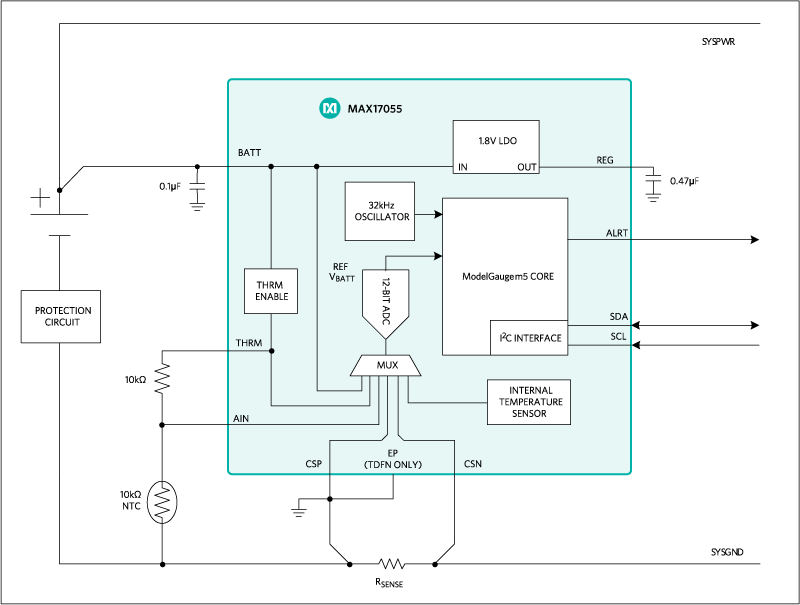
Using a fuel-gauge IC is an alternative to the voltage-divider method. Fuel-gauging methods are very complex and, therefore, more expensive; however, they can be quite accurate. The total resistance of the resistor divider on the FLORA is 160kΩ, so it consumes ~23µA when connected to a Li+ battery. We didn’t want to replace the resistor dividers with something that consumed more power, so we settled on a fuel-gauge IC that uses only 7µA of current. Maxim’s MAX17055 uses the company’s fuel-gauge algorithm called ModelGauge™ m5, which combines the two most common methods of fuel gauging—coulomb counting and open-circuit voltage measurement—to report a battery’s SOC with only a 1% error. Another innovative feature of the ModelGauge m5 technology is that it includes an EZ configuration feature that eliminates the need for battery characterization, which most fuel-gauge ICs require.
 Figure 4. Maxim’s MAX17055 fuel-gauge IC utilizes ModelGauge m5 technology to determine battery charge.
Comparison Tests
We performed a series of tests to compare the original voltage divider on the FLORA to Maxim’s MAX17055 fuel-gauge IC. After taking the resistor divider measurements, we replaced the components with the MAX17055. To maintain consistency for the test results, we used one 150mAhr battery for all tests. First, we performed a baseline test by discharging the battery with a constant load, observing the results for both the voltage divider and the fuel gauge. Next, we used a more realistic, pulsing load to discharge the battery, and observed the accuracy of the voltage divider and the fuel gauge.
Baseline Test Using Resistor Divider
The output of the voltage divider on the FLORA simply helps you determine the terminal voltage of the battery; therefore, some calculations must be performed to translate the voltage reading to a percent charge that is easy to understand. First, we used a constant load of 125mA to completely discharge the battery. The battery voltage was reported at constant time intervals. Figure 5 shows the average cell voltage of five discharge cycles as the battery is discharged completely. Then, we used two different methods to determine the SOC of the battery during discharge from the output of the voltage divider.
 Figure 5. Average cell voltage of a battery over time as it is discharged with a constant current load.
In our first method, we correlated the voltage of the battery to some percentage of charge remaining. The 150mAh battery used for testing can be charged to a maximum of 4.2V, so this voltage was correlated to 100% charged. The minimum discharge voltage of the battery is 3.0V, so this voltage was correlated to 0% charged. From these two estimations, we used a linear equation to transform the battery cell voltage reported from the voltage divider on the FLORA to an approximate percentage of charge remaining. This is our "linear" approximation method. While it’s easy to form a relationship between battery cell voltage and SOC, it is not very accurate because, as seen in Figure 5, the battery cell voltage does not decrease linearly during discharge.
The next method is based on charge consumed by measuring the discharge time of the battery. With a constant load current, the amount of time passed is proportional to the amount of charge consumed (coulomb/second × second = coulombs), hence SOC (coulombs). In this case, a 100% charge is correlated to the start time of the test when the load is first placed on the battery. A 0% charge is correlated to the time when the device shuts down. To form an accurate model using this method, we found an average of five discharge tests. From there, we created a fourth-order trendline for the average SOC. A higher order polynomial would become impractical to compute for every battery voltage sample. The equation of this trendline was used to correlate battery voltage to SOC. The solid line in Figure 6 shows the average SOC curve, while the dotted line represents the trendline. This is our “polynomial” approximation method; see Figure 6 for the equation for the trendline.
 Figure 6. Fourth-order polynomial that can be used to approximate the voltage of a battery to percentage of charge
remaining.
Baseline Test Using the MAX17055
Finally, we compared these two approximations to the output of Maxim’s fuel-gauge IC, the MAX17055. The MAX17055 outputs many results, including cell voltage, load current, age, and temperature. It also uses the ModelGauge m5 algorithm to approximate the SOC of the battery. Discharging the battery with a constant load produced a linear decrease in SOC over time—this was the result we were hoping to see. The purple graph in Figure 7 shows the readings from the fuel-gauge IC, along with the linear and polynomial approximations described above.
 Figure 7. Charge of a battery when discharged with a constant current based on linear model from the voltage divider,
polynomial model from the voltage divider, and SOC from the fuel gauge.
From Figure 7, it is obvious that each of the approximations assumes that the battery is 50% full and 25% full at different times. Figure 8 shows the colors of the NeoPixels as the battery discharged. In the bar graph on the right, you can see a comparison of the percent runtime for each of the models we used versus the desired result we expected to see. The bar graph of the linear model shows that the NeoPixels remained green, indicating > 50% charge, even when the battery was almost to a 25% charge!
 Figure 8. The graph on the left shows the NeoPixel colors during discharge using each model. The graph on the right
illustrates the same data in a form that is easily comparable to the desired result.
In this case, the polynomial model and the fuel gauge both reported fairly accurate results. However, the actual design did not use a constant load current. Even if a model can work for constant current load, it may break when switching to a more realistic pulsed load.
Pulse Load Test on Three Fuel Gauge Methods
To truly test the capabilities of all three fuel gauge methods, we had to run another experiment with a realistic pulsing load current placed in the system. The load alternated between drawing 125mA for four minutes and drawing 60mA for two minutes. Many systems have a much larger difference between standby and active current consumption, which would exacerbate the results of this test. We used the same three methods as for the baseline test above—linear model based on the voltage divider, polynomial model based on the voltage divider, and the SOC reported by the MAX17055. Figure 9 shows the results of the pulse load test. The purple line is the fuel gauge’s reported SOC over time. The blue line is the approximated SOC from the voltage divider using the linear model, while the green line is approximated using the polynomial model.
 Figure 9. Charge of a battery when discharged with a constant current based on linear model from the voltage divider,
polynomial model from the voltage divider, and SOC from the fuel gauge.
Figure 10a and Figure 10b provide over views of the same data, each showing the color of the NeoPixels during discharge.
 Figure 10. The color of NeoPixels from each model when discharging a battery with pulsating load.
Both methods that used the results of the voltage divider to approximate the remaining battery capacity introduced errant pulses in their outputs. These results are clearly inaccurate and produce confusing results that alternate between green and yellow and yellow and red. This demonstrates the effect of a change in load on the terminal voltage of the battery. The sophisticated algorithm in Maxim’s fuel gauge shows the immunity to the loading effect and continues to output a linear decrease in SOC matching the actual SOC of the battery. Since load current in an application is constantly changing, our findings only emphasize the importance of using a fuel-gauge IC like the MAX17055.
Conclusion
When using their portable electronic devices, consumers want to be able to trust the accuracy of the remaining battery charge. There are some simple, inexpensive methods to estimate the battery SOC, but their results are far from accurate. A method like the voltage divider described and used on the FLORA reports data that varies greatly with load. This could leave me thinking I have enough battery capacity left to walk an additional 10 minutes, only to have my dog’s tracker shut down before I’ve located her. More advanced fuel-gauge ICs, like the MAX17055, provide accuracy that I can trust. My experiments have convinced me that a fuel-gauge IC is worth every penny.
A similar version of this application note appeared on Electronic Products on November 27, 2017.


