Give Your Wearable’s Micro Some Quality Sleep Time
要約
Until recently, efforts to save power in wearables have focused on reducing the power consumed by devices while in active mode. A common oversight is that even in low power or sleep mode, some critical device functionality such as timekeeping must be maintained by the microcontroller. We review how wearable devices keep track of time and introduce an alternative real-time clock solution that extends battery life by significantly reducing timekeeping current during sleep mode.
IntroductionMaximizing the battery life of a wearable electronic device (Figure 1) requires some finesse. It’s crucial that power is primarily consumed only while performing critical tasks. Until recently, most efforts to save power have focused on reducing the power consumed by devices while in active mode. A common oversight is that the longer the device spends in low power or “sleep” mode, the longer the battery life will be extended before requiring a recharge.
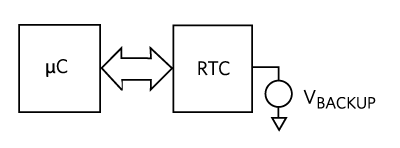
However, even in sleep mode, some critical device functionality must be maintained. One such function is timekeeping. In this design solution, we will review the way wearable electronic devices keep track of time and introduce a solution to extend battery life by significantly reducing timekeeping current during sleep mode. The Real-Time ClockElectronic devices perform tasks in response to the periodic oscillation of an electrically varying digital voltage signal or clock signal. On the other hand, human time (also known as “real” time) is measured in seconds, minutes, hours, days, months, and years. For electronic devices to perform their tasks when required by the user, they must store a digital representation of real time, which is then kept in synch using the digital clock signal. Real-time information is maintained by a real-time clock (RTC) circuit, usually located within the device microcontroller. However, if the device battery, which powers the microcontroller fails, then real-time information will be lost and will need to be reset after power has been restored. While many wearable devices have the functionality to reset the time using a wireless connection to a remote master, this type of communication places an extra power drain on the battery (and obviously can only occur if a wireless signal is available). In such a scenario, the only (and clearly less desirable) alternative is for the user to manually reset the time. Another caveat of having the RTC circuit located in the microcontroller is that the microcontroller can never be fully powered down. Clearly, even when the device is in sleep mode the RTC information must be maintained. A microcontroller will typically consume 600nA of current with its RTC enabled. External RTC CircuitAn alternative approach for wearable devices is to use an external RTC circuit (Figure 2) that interfaces to the microcontroller. While the device is in normal operation, this external RTC circuit is powered by the main battery. However, in the event of a main battery failure, the external RTC switches to a “backup” power source. This backup source may be another battery, or if space is at a premium, a supercapacitor. One advantage of this approach is that real-time information is maintained until the main battery is replaced or recharged. A second advantage is that the microcontroller is completely powered down while the device is in sleep mode. A typical stand-alone RTC circuit consumes less than 200nA, which includes power savings of over 90% when compared to the 2µA required to keep a typical microcontroller’s RTC circuit active in sleep mode.
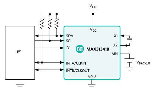
While minimizing the current consumption of the external RTC circuit is obviously important, it’s also critical to be mindful of the impact of an extra IC on system board space. Depending on the exact design specification, there may be a trade-off to be made between current consumption and board space. Striking the Best BalanceThe low-current, real-time clock with I2C interface shown in Figure 3, achieves the twin goal of very low power consumption (180nA timekeeping) and small size (2mm x 1.5mm, 12-bump WLP).The size advantage (smaller than any similar RTC) makes it a viable solution even when board space is at a premium.
Unlike solutions which have an integrated crystal, this part uses an external crystal to generate its clock signal. This allows selection from a range of crystals with a load capacitance of 6pF and an equivalent series resistance up to 100kΩ (for minimal current consumption). This is particularly beneficial given the board area constraints of wearable devices, where the shape and size of the crystal can be critical. The integrated capacitive loading ensures tight timekeeping accuracy, which can be negatively impacted if a lower tolerance external capacitor is used. A programmable threshold voltage allows seamless switching from the main battery supply to the backup power source. SummaryIn this design solution, we have reviewed the need for portable electronic devices to keep track of real time, even when they are in sleep mode or in the event of main battery failure. We considered the shortcomings of using the device microcontroller to keep track of real-time information and then illustrated the advantages of using a low-power, external RTC in a small footprint. In addition to smart wearables, it is also well suited for portable medical and healthcare applications including point-of-sale equipment, telematics, portable instruments, and portable audio. GlossaryIC: Integrated Circuit RTC: Real-Time Clock. Integrated circuit that contains a timer that supplies the time of day (and often, the date). An RTC generally contains a long-life battery to allow it to keep track of the time even when there is no power applied. Sleep Mode: Power-saving mode of operation in which devices or parts of devices are switched off until needed. Supercapacitor: A supercapacitor is a high-capacity capacitor with capacitance values much higher than other capacitors (but lower voltage limits) that bridge the gap between electrolytic capacitors and rechargeable batteries. WLP: Wafer-Level Package. Wafer-level packaging (WLP) allows an integrated circuit (IC) to be attached to a printed circuit board (PCB) face-down, with the chip’s pads connected to the PCB pads through individual solder balls. |
| ||||||||||
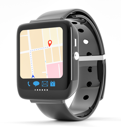
 Figure 1. Wearable smart watch.
 Figure 2. External RTC interfaced to a microcontroller.
 Figure 3. MAX31341B RTC typical operating circuit.


