要約
The DS1869 is a 64-position digital potentiometer with \"up/down\" control, which allows adjustment in a manner similar to mechanical potentiometers. The device has three modes of operation which allow control either from a single pushbutton, double pushbutton, or control from a microprocessor or microcontroller, depending on how the chip is hardwired into the circuit. On power-up, the potentiometer \"senses\" the configuration it is in and switches to the appropriate mode of operation. Configuration is critical, as it is possible to attempt to configure the device for one mode of operation, but actually force it into the wrong mode. This application note details the fine details of configuration to avoid this sort of application problem.
DS1869: Dual, Single, and Digital
The DS1669/DS1869 can be configured to operate in three modes. The Dual Contact Mode requires two signals, one to increment the wiper position and one to decrement the wiper position. The Single Contact Mode and Digital Input Mode only require one signal to both increment and decrement the wiper position. Of the three, the Dual Contact Mode offers the most control over the wiper position.
Dual Contact Mode
To enter Dual Contact Mode, the DC input must be floated on power-up. The UC and DC pins can be configured to receive signals from pushbuttons or from microprocessor outputs. The Dual Contact Mode offers the best control over the wiper. The two input pins, UC and DC, increment and decrement the wiper position, respectively. To cause the wiper to move 1/64th of the total resistance, a low-going pulse of at least 1ms in length is required. The UC and DC pins are internally tied to V+ by 100kΩ pull-up resistors, and are internally debounced. The signals to UC and DC must be inactive (high) for 1ms between pulses.
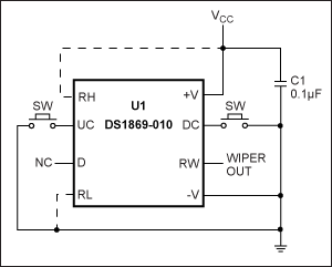
When the DS1669 or DS1869 is configured in the Dual Contact Mode with pushbuttons (Figure 1), the operator can control when and in what direction the wiper will move. Once the wiper reaches the upper or lower limit, it will not move any further. Once incremented to position 64, the wiper will not move any further by pulsing the UC pin. Once decremented to position 0, the wiper will not move any further by pulsing the DC pin. Using this method, a known starting position can be attained by incrementing or decrementing the wiper position to either limit, then moving the wiper to the desired position.

Figure 1. Dual contact mode using pushbutton inputs.
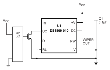
Another option is to use the output pins of a microprocessor to pulse the UC and DC pins. A NMOS FET must be used to interface with the DC pin so that it is floating on power-up. Figure 2 shows how this circuit would look.

Figure 2. Dual contact mode using microprocessor signals.
The timing requirements for the pulses are the same as with the pushbutton setup. But by using the microprocessor, the UC and DC inputs can be quickly pulsed to reach either limit and thus a known position.
The microprocessor can then pulse the inputs pins to place the wiper at a desired position. It is possible to hold the inputs low and step through the wiper positions. However, this method is slower than sending individual pulses. After pulling either the UC or DC input low, there is a 1 second delay before the wiper will move. After that 1 second, the wiper will change positions once every 100ms until it reaches one of the limits, then it will stop stepping. So to traverse the entire length of the resistance would take 7.3 seconds (1 second + 63 positions x 100ms).
Single Contact Mode
The DS1669/DS1869 can also be configured to operate in Single Contact Mode. The DC pin must be tied to V+ in order to enter Single Contact Mode. The UC pin can be tied to a pushbutton or a microprocessor output. The signal requirements for the input to UC are the same as for the Dual Contact Mode with the exception that if there is an inactive period of 1 second or more between pulses, the direction the wiper position will step is reversed. Another characteristic of the Single Contact Mode is that the direction of the wiper stepping will reverse when either the upper or lower limit of the resistance is reached. For instance, if the wiper is being decremented and the position 0 is reached, the next pulse will set the wiper to position 1. The same occurs at the upper limit. When the wiper is incremented to position 63, the next step will be to decrement to position 62. The control achieved with this configuration is not as great as the Dual Contact, and prohibits the application from establishing a known position. This may not be a problem for some applications like a LCD brightness adjustment, which relies on the user to determine when the appropriate level of light has been reached.
Here are two circuits using the Single Contact Mode. Figure 3 shows the pushbutton interface and Figure 4 shows the microprocessor interface.

Figure 3. Single contact mode using a pushbutton input.

Figure 4. Single contact mode using a microprocessor signal.
Digital Input Mode
The Digital Input Mode provides the same amount of control over the wiper as the Single Contact Mode, but at a much faster rate. The Digital Input Mode requires a 1µs pulse with an inactivity time of 250µs. While faster than the Dual and Single Modes, the control over the wiper position is the same as the Single Mode. Again, this mode of operation is good for applications where there is some external indicator (light level or audio level) of the wiper position. Figure 5 shows a typical Digital Input Mode.

Figure 5. Digital input mode.
Conclusion
Both the Single and Dual Modes have the same speed requirements for the pushbutton controls. It is suggested that if there is space on the application for two buttons, then the Dual Contact Mode should be used to provide accurate control of the wiper. If only one pushbutton is available, the Single Contact Mode can be used to adjust the wiper position, but at the cost of precise wiper control.
For speed, the Digital Input Mode is the best option. While this mode offers the fastest adjustment of the wiper, it does not provide accurate control of the wiper. There is no way to establish a known wiper position. If there is some external indicator of the wiper position, like a light, then this is probably the best solution. However, if the wiper position must be established, then the only option is to use the Dual Contact Mode with either pushbuttons or the NMOS interface to a microprocessor.


