Cover Glass and Aperture Design for Automotive Gesture Sensor
要約
This application note shows how to design cover glass and apertures for an automotive gesture sensor. It minimizes optical crosstalk.
Introduction
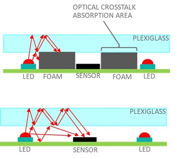
The application note gives guidance on how to design the optomechanical section for the MAX25205and MAX25405 gesture sensors. A major design concern for an infrared (IR) gesture detection system is optical crosstalk from the LED to the sensor (see Figure 1). This optical crosstalk gets much worse when mounted behind glass. Optical crosstalk can significantly reduce the gesture detection range.
There are several paths from the LED to the sensor that can cause crosstalk. These paths consist of direct, reflected and light reflected in the cover glass. The direct and reflected path is easy to mitigate. An optical barrier is placed between the LED and the sensor to block light. The light that gets reflected in the cover glass is more difficult to mitigate. In this case, foam is placed under the cover glass between the sensor and LED. This foam absorbs the light that is trapped in the cover glass. The foam also acts as an aperture for the sensor and the LEDs.
Mechanical Stackup for Plexiglass
Figure 2 shows the mechanical stackup for plexiglass. The cover glass used is IR transmissive plexiglass. It blocks visible light below 750nm and is transmissive above. The part number is Plexiglas IR acrylic 3143. The polyurethane foam in between the Plexiglas and PCB is Rodgers Poron 4701-30. It is very soft and easily compressed. This material is used to absorb undesired reflections, refractions, and direct light.
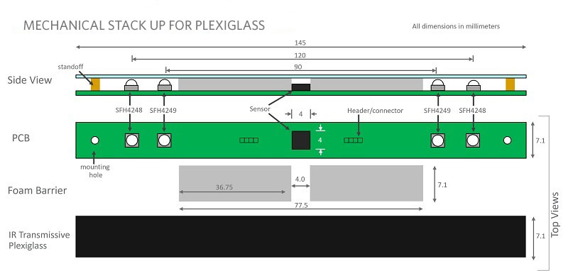
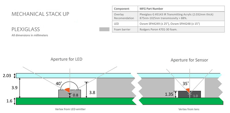
Figure 3 shows more detail around the LED and the sensor. A 35-degree aperture is placed around the sensor, while a 40-degree aperture is placed around the LEDs.
Mechanical Stackup for Glass
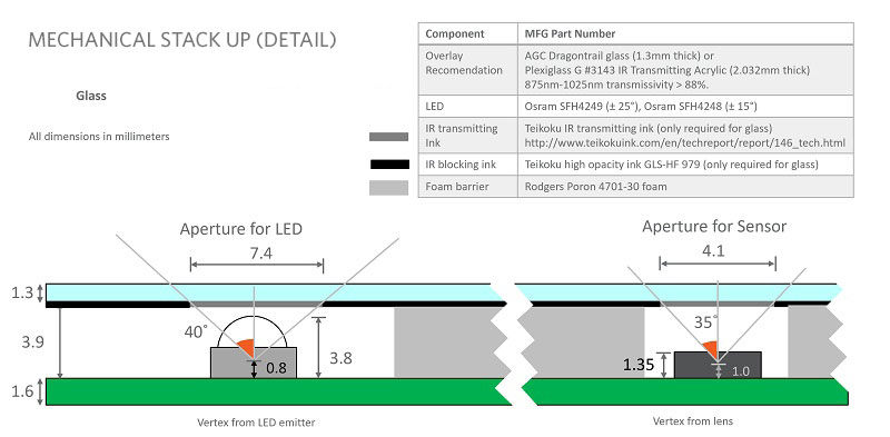
Figure 4 shows the mechanical stackup for glass. The IR blocking ink is used to create the apertures while an IR transmissive ink hides the LEDs and sensor behind the glass.
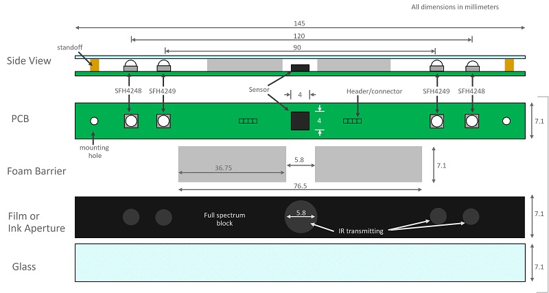
Figure 5 shows more detail around the LED and the sensor. A 35-degree aperture is placed around the sensor while a 40-degree aperture is placed around the LEDs. IR ink can be used to create the aperture. IR transmissive ink can be used to hide the LED’s. There is also IR transmissive films available such as 3M’s sensor camouflage film 1921-CMBK.
