要約
In this design solution, we learn how a 24-bit sigma-delta ADC touchscreen interface is a fail-safe method for successfully sensing human touch (gloved or not) through applied pressure.
Introduction
Vehicle infotainment (information and entertainment) clusters traditionally contained a few knobs for climate control and a radio control to listen to your favorite tunes (Figure 1). Modern infotainment clusters implement touch screens as the main human-machine interface (HMI), exponentially expanding the configurability of the vehicle to the driver’s specific preferences. Drivers now have access to detailed diagnostic information including driving habit analysis, navigation, audio experience expanding into Bluetooth®, universal serial bus (USB) and satellite connections, as well as climate and other advanced vehicle settings. Many of these features, in addition to pairing with a smartphone’s cellular network, continue to expand the possibilities of the automotive infotainment cluster.

Figure 1. 20th-century automotive controls.
Touch screens are the enabling technology providing extended configurability by eliminating the mechanical size constraints placed on traditional infotainment systems. Touch screens create a dynamic interface that provides dedicated menus for each of the above-mentioned features. There are two leading technologies: piezo-based screens and capacitive-based screens.
This design solution delves into these two technologies to explain their fundamental principles of operation, highlighting the benefits and drawbacks of each, and to determine which is the superior architecture for automotive applications.
Infotainment Cluster Using Capacitive Arrays
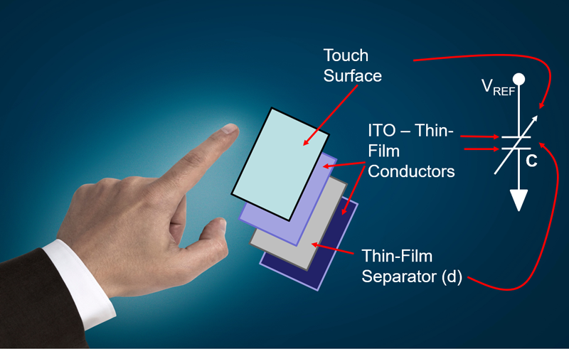
Capacitive-sensing systems have increased in popularity with their adoption into tablets and smartphones. A capacitive touch-screen controller (CTSC) uses the conductive touch of a human finger with a specific interface to receive the input signals. The construction of a capacitive element involves two plates, in close proximity, with a dielectric between them (Figure 2).

Figure 2. A single touch-screen capacitor’s construction has four layers.
In Figure 2, the ITO (Indium Tin Oxide) conductors create the capacitive plates, and the dielectric between the plates is the thin-film separator layer. The finger applies pressure to the touch surface to lessen the distance (d) between the ITO layers. The lessening of this distance increases the capacitance value (Equation 1).
The capacitance value in Figure 4 is equal to:

Where:
C is the capacitance in farads
A is the adjoining area of the ITO plates (m2)
ε0 is the electric constant = 8.854 × 10⁻¹²F/m
εr is the dielectric constant of thin-film separator
d is the separation distance between the plates (m)
Equation 2 describes the charge (Q) on the capacitor’s plates as it relates to the capacitor (C).
Q = VREF × C (Eq.2)
Where:
Q is the charge in Coulombs, 1C approx. 6.24 × 10¹⁸ electrons
VREF is the reference voltage in volts
C is the capacitance in farads
The capacitor sensor responds to heavy or lightly applied pressures that allow accurate sensing across a wide dynamic range. A CTSC can sense subtle changes by placing an additional capacitor across the touch-screen capacitor. In doing so, the total capacitance is a sum of the touch-screen capacitor (CTOUCH) and the controller’s capacitance (CCTSC) per Equation 3 . Additionally, the total charge is a sum of the touch-screen charge (QTOUCH), and the controller’s charge (QCTSC) per Equation 4.
CTOT = CTOUCH + CCTSC (Eq. 3)
QTOT = QTOUCH + QCTSC (Eq. 4)
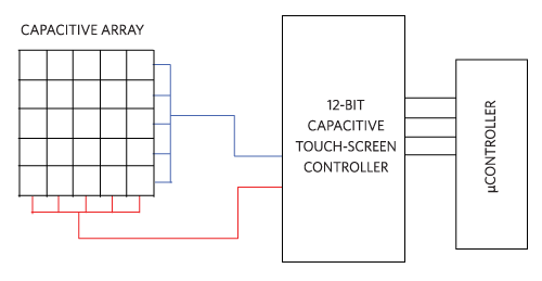
The CTSC evaluates these changes across the capacitor array, to map the overall force magnitude and coordinates (Figure 3).

Figure 3. A capacitive-array touch screen uses a 12-bit capacitive touch-screen controller to collect data.
The capacitive element in the touch screen is an array which contains numerous capacitors that require sensing. Typical CTSCs incorporate 12-bit analog-to-digital converters (ADCs). This conversion technique effectively captures the activity on the capacitive array.
Automotive capacitor touch systems do have a few limitations. If the driver of the automobile is using gloves, the capacitive touch screen may not accommodate the glove material since the dielectric material in most gloves make it difficult for the touch sensor to detect a touch.
Touch accuracy is an essential characteristic in touch sensor design. In a touch-screen keyboard application, the tightly packed capacitors make precision difficult. One way to achieve high accuracy is to add more controller sensor channels to support a higher touch-sensor grid density. But, the penalty for this type of system is to increase the CTSC and capacitor array pins. In addition, this will require more sensor channels, more traces running along the border of the touch screen, and a bezel-width capacitive array increase.
The automotive environment is rich with electromagnetic interference (EMI) sources. Any small interference, such as an EMI signal, will appear in the sensor’s output or in the PCB traces between the sensor and CTSC. The longer the cable or traces to the sensor, the greater the EMI interference will be due to increased coupling opportunities. This can be improved by using shorter PCB traces.
Many CTSCs have adjustable sensitivity capability, which facilitates this difficult problem. However, an increase in the touch controller's sensitivity may cause unintentional triggers even when the driver is gloveless.
Infotainment Cluster Using Piezo Sensors
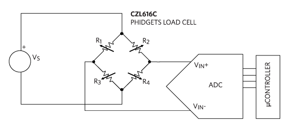
Piezo materials are materials that change their electrical characteristics based on mechanical deformation commonly known as strain. The most common resistive touch-screen architectures use piezoresistive materials that change their resistance based on the mechanical strain applied. These devices are known as load sensors. The Wheatstone resistive bridge is the appropriate model for this sensor (Figure 4).

Figure 4. Resistive Wheatstone model of a load cell sensor.
In Figure 4, the Phidgets CZL616C micro load cell measures force in one direction. The nominal values of R1, R2, R3, and R4 are 1kΩ and the rated output is 800µV/V. The odd number resistors (R1 and R3) increase their resistance with applied force, while the even number resistors (R2 and R4) decrease their resistance. These changing resistor values, in conjunction with the source voltage (VS), create a change in the input voltage to the ADC.
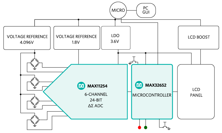
In a four-sided infotainment touch screen, there are four load cells, one for each corner. These piezo sensors respond to heavy or light applied pressures allowing accurate sensing across a wide dynamic range. It is possible to use a 12-bit or 16-bit ADC with an amplifier front-end in this system. However, these converters would be unable to provide measurements of subtle load cell outputs from light brushing or air currents in the microvolt range. A multi-channel, 24-bit ΔΣ ADC is better suited to this system, since it can sense the small voltages for the four load cells (Figure 5).

Figure 5. A resistive touch screen uses a four-channel 24-bit ΔΣ ADC to collect the data.
In Figure 5, the 6-channel MAX11254, 24-bit ΔΣ ADC senses at 200sps to 110nVRMS accuracy, with the PGA gain equaling 128 (see the MAXREFDES82). This circuit can scan each channel for the force magnitude and coordinates approximately every 10ms. The microcontroller evaluates the forces applied to each load cell to map to the total force magnitude and coordinates.
As for the EMI sources, the sigma-delta ADC differential input’s large common-mode rejection ratio (CMRR) easily rejects these signals.
For this system, a gesture is as simple as a single finger swipe enabled by a system host microcontroller that can readily recognize simple gestures like pinch, pull, zoom, rotate, double, or triple tap.
Conclusion
The increasing demands of the automobile driver for easy control of the infotainment system continues to guide the look and feel of the next-generation of infotainment clusters. Although the knobs and levers are not completely gone, the emerging alternative is a touchscreen interface that provides greater control and flexibility.
At the front end of the automobile touch screen is either a resistive load cell or capacitive array. The complete picture of capacitive array sensing requires a 12-bit CTSC. This interface senses the human touch through applied pressure, however, gloved fingers and tightly packed sensors present errors in the measurement system. The best solution for greater accuracy is through resistive load cell sensing that requires the use of a 24-bit ΔΣ ADC. This provides the touch screen interface a fail-safe method for successfully sensing human touch, gloved or not, through applied pressure.
Learn More
Resistive Bridge Basics: Part One - Tutorial
 PGA、デルタシグマADC、SPIインタフェース内蔵


