3-in-1 Device Replaces Battery Charger, Overvoltage Protection and PowerPath Manager for USB/Battery Powered Devices
3-in-1 Device Replaces Battery Charger, Overvoltage Protection and PowerPath Manager for USB/Battery Powered Devices
著者
Andy Bishop
2007年06月01日
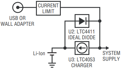
An efficient Li-Ion battery powered system requires at least three distinct circuits to control the power path between the load, the battery and the power source (see Figure 1). The minimal circuit requirements include:
- a battery charger,
- a power switch to select powering the load from either the battery or the wall adapter (when present),
- and a current regulator for the wall adapter/USB input.

Figure 1. Battery charger current-limit and ideal diode supply connections with intermediate voltage bus.
This, of course, assumes that the load draws power from a communal power bus, as opposed to attaching directly and exclusively to the battery. A direct-to-battery topology might be simpler, precluding the need for the power path controller and regulator, but it is far less efficient and significantly more restrictive. For instance, if the battery is fully drained, no power can be delivered to the load, even if wall adapter power is available.
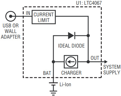
The LTC4067 Li-Ion charger and PowerPath™ controller combines the efficiency, flexibility and robust nature of a 3-chip solution with the simplicity of a direct-to-battery topology by replacing three components with a single device, as shown in Figure 2. The LTC4067’s advanced topology battery charger optimizes power utilization while limiting input current to a programmable level, making it ideal for USB powered applications.

Figure 2. Intermediate voltage bus supply connections with the LTC4067.
Working with USB Port Current Limits
In applications where input current consumption is constrained, the LTC4067 is able to satisfy USB power requirements. Take the example of a portable device with a disk drive that draws power from either a battery or the USB. Peak current consumption may readily exceed USB limits when the disk is spinning up. In this situation, the LTC4067 optimizes power management by sharing the load between the battery and the USB, while limiting the current from the USB port. When load current decreases, the LTC4067 automatically switches over to charge the battery with any excess USB current that is not consumed by the load.
The LTC4067’s input current limit is programmable via a resistor at the CLPROG pin. Control inputs ILIM0 and ILIM1 are used to set USB high power, low power or suspend operating modes—or allow for much larger current limit when powering from a wall adapter. The LTC4067 also provides instantaneous USB current and charge current monitoring, allowing the application to perform advanced gas-gauge functions.
Working with Unregulated Wall Adapters
With the addition of an external high-voltage PFET, the LTC4067 provides an automatic overvoltage protection function that allows the LTC4067 to automatically disconnect itself in the event that the wrong wall adapter is applied.
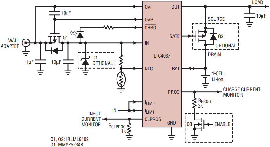
Figure 3 illustrates an application where the LTC4067 charges a single-cell Li-Ion battery from a 1A wall adapter. The overvoltage protection circuit includes the OVI and OVP pins of the LTC4067 and an external PFET in series with the IN pin. The PFET serves to disconnect the LTC4067 from potentially damaging overvoltage conditions. When the OVI input senses a voltage greater than 6V, the OVP output pulls up to disable the PFET. When OVI falls below this threshold, the OVP output falls low, turning on this PFET. Note that the body diode of this PFET is connected so that it does not forward bias when an overvoltage condition exists. While the overvoltage condition persists, the input power path is disabled, but system power is provided by the battery. A 10nF capacitor placed from OVI to OVP ensures that the PFET is quickly disabled in the event that fast edges occur when the wall adapter is suddenly hot-plugged. An optional, low power Zener diode is also recommended in the event that voltage surges occur after the device is powered.

Figure 3. Li-Ion charger/controller with overvoltage protection.
In the example of Figure 3, the input current limit from the wall adapter is programmed to 1A with a 1k resistor from CLPROG to GND, assuming ILIM0 and ILIM1 are held high, or 200mA if ILIM0 and ILIM1 are both held low. The charge current is independently programmed to 500mA via the 2k resistor from the PROG pin to GND.
An optional second external PFET connected between OUT and BAT serves as a high performance ideal diode to connect the load to the battery with an extremely low impedance. The GATE output pin enables this ideal diode when the wall adapter disconnects or when the load demands more current than the wall adapter supplies. Note that this PFET is connected so that the internal body diode from drain to source does not forward bias when the voltage at OUT is greater than the voltage at BAT.
The LTC4067 allows for instantaneous monitoring of both input current and charge current for advanced gas gauge functions by measuring the voltages at the CLPROG and PROG pins, respectively. The optional NFET (Q3) tied in series with the PROG pin resistor serves to engage a low power shutdown mode, where total quiescent current drops to less than 20µA.
Full Featured USB Li-Ion Charger
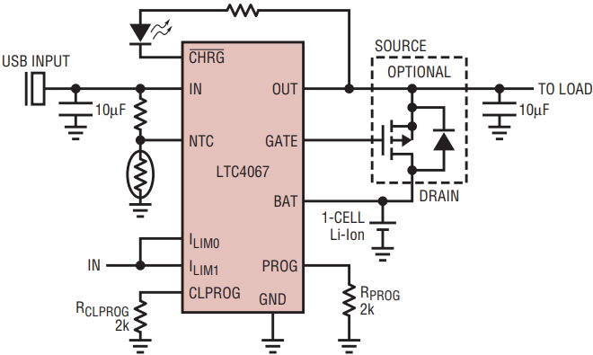
Figure 4 illustrates an application for charging a single-cell Li-Ion battery directly from the USB, conforming to the USB requirements for low power (LPWR), high power (HPWR), or self-powered functions. Here, the LTC4067 ensures that the load at OUT sees the USB potential when the USB port is present. When the USB port is removed, the load powers from the battery through an internal 200mΩ ideal diode. Optionally, for more demanding applications, an external PFET driven by the GATE pin improves performance by reducing the series resistance of the ideal diode.

Figure 4. USB battery charger/controller.
The 2k resistor at the CLPROG pin ensures that the maximum current drawn from the USB input port remains below the maximum allowed depending on the permitted power allocation: 500mA for HPWR USB function or 100mA for LPWR USB function. By driving the ILIM0 pin low and the ILIM1 pin high, the LTC4067 complies with the USB SUSPEND specification, whereby the load at OUT powers from the battery and the only current drawn from the USB port is due to the two series NTC pin resistors.
The 2k resistor at the PROG pin selects 500mA for the charge current, automatically charging a single-cell Li-Ion battery following a constant-current/constant-voltage (CC/CV) algorithm with a built-in timer that halts charging two hours after the charger enters constant-voltage mode. Note that actual charge current depends on the load current, as the charger shares the USB current with the load.
During a charge cycle, the CHGB status pin signals that the battery is charging in constant-current mode by pulling to GND through an open-drain drive output capable of driving an LED for visual indication of charge status. When the charge current drops to less than about 9% of the programmed charge current and the battery is above the recharge threshold (4.1V), the CHGB pin assumes a high impedance state (although top-off charge current continues to flow until the internal charge timer elapses). Bad battery and battery out-of-temperature conditions are also flagged with the CHGB pin by a series of flashing pulses.
If the load demands more current than allowed by the USB current limit, the charge current automatically scales back. As the load demands more current than available from the USB port, charge current decreases to zero, at which point an ideal diode function from BAT to OUT turns on as the OUT voltage drops below the BAT voltage. When the ideal diode engages, the battery charge cycle pauses, and the load draws current from both the USB port and the battery. When the load current decreases such that the OUT voltage rises above the BAT voltage, the charge cycle restarts where it left off.
At any time, the user may monitor both instantaneous charge current and instantaneous USB current by observing the PROG pin and CLPROG pin voltages respectively.
Conclusion
The LTC4067 satisfies the needs of voltage sensitive battery operated devices, replacing as many as three separate devices. With accuracy better than ±0.4% on the battery float voltage, the LTC4067 is ideally suited for demanding high-precision applications. The LTC4067 offers both a power management strategy that complies with USB port specifications as well as providing an advanced battery charger. The LTC4067 also offers overvoltage protection up to 13V, to protect itself as well as system devices in the event that an incorrect wall adapter is attached.


