100V Micropower Voltage Monitor Provides Flexible Monitoring of Positive and Negative Rails Simultaneously
100V Micropower Voltage Monitor Provides Flexible Monitoring of Positive and Negative Rails Simultaneously
著者
Sal Afzal
2015年07月22日
Flexible supply monitoring that eases design and provides high accuracy, at a low current cost, is in high demand in today’s power conscious world. Typical supply monitors comprise a comparator with a reference, and an external divider to set the exact trip points. Unfortunately, the divider can, itself, draw more current than the supply monitor. The reason being that, since leakage currents can compromise accuracy, small value resistors are typically used as they are less sensitive to leakage currents. As a result these resistor values can have significant current flowing through them across a wide operating range.
Essentially, the problem is twofold: first, precision resistors are needed to preserve accuracy, and 1% resistors are typically only available up to 3.32MΩ. Second, high value resistors are more sensitive to leakage currents resulting in a drop in accuracy. So it would seem that a micro power solution that operates across a wide operating range is made impossible by these problems.
The LTC2966, dual channel micro power voltage monitor, overcomes these issues by including a precision trimmed 80MΩ internal divider along with comparators for each channel. Since the divider is internal to the IC, it eliminates board leakage issues. A reference voltage is provided to allow the thresholds of each channel to be set independently. The advantage of this topology is that the comparator reference inputs keep supply current burden to a minimum by operating at a low voltage and adjustments are made there with external resistors of commercially available values. The LTC2966 is designed to provide an accuracy of 1.4% while monitoring two supplies of up to 100V with just a 7µA supply current, plus a small overhead for the reference divider. The LTC2966 also provides selectable output signal polarity so that it can be used with active low or active high systems.
Monitoring split supplies can become cumbersome, especially when using separate ICs to monitor each rail. While the LTC2966 is designed to monitor two positive supplies, such as redundant 48V, it can also be adapted to monitor split supplies, such as shown in Figure 1 of the datasheet. However, the design equations were left as an exercise for the reader. The selection of divider resistors for split supplies is similar to the procedure shown in the LTC2919 datasheet, a product that monitors either positive or negative supplies with equal ease.
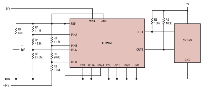
Figure 1. LTC2966 ±24V Monitoring Circuit.
This article shows the derivations of design equations for a three resistor solution and includes a design example for monitoring ±24V supplies which are typical of many servo motor driver applications.
In the circuit shown in Figure 1, Channel A is used to measure the +24V supply rail. Positive supply monitoring is discussed in detail in the LTC2966 datasheet in the threshold configuration section and will not be discussed here. Channel B is used to monitor the –24V supply rail by taking advantage of the independent reference voltage, connecting the VINB internal resistive divider to VREF and selecting the 5× VIN range (Figure 2). A detailed analysis of how to configure the LTC2966 for negative rail monitoring follows.
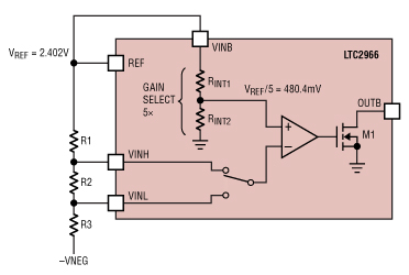
Figure 2. LTC2966 Internal Divider and Reference.
In a conventional (positive) circuit, VINB is the input, i.e VINH/VINL set the threshold. In a negative monitoring circuit, on the other hand, VINB sets the threshold while the input is applied to the VINH/VINL pins. The range selection pins RS1 and RS2 help select the gain and as a result sets the thresholds at the VINH/VINL pins using the VINB pin voltage. In our example a 5× range selection sets a threshold of 480.4mV as shown below.
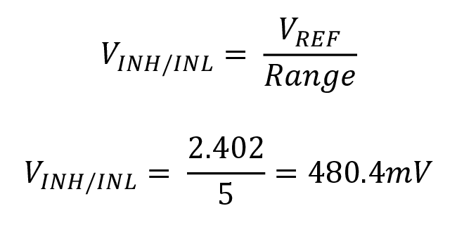
The equivalent circuit for VTHR, the rising edge (negative voltage increasing in magnitude) is shown in Figure 3.
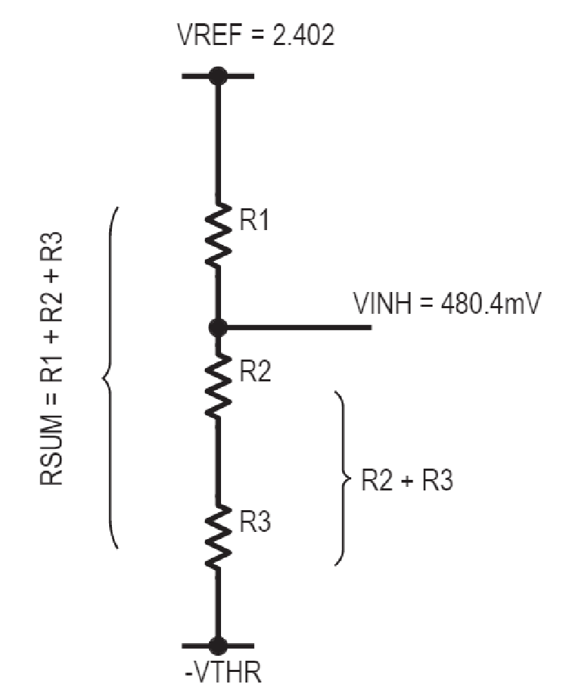
Figure 3. Rising Edge.
To maintain accuracy we want the current in the resistive divider to be significantly greater than the leakage current of the comparator inputs (1nA) but small enough not to burn much power. As a rule of thumb it should be at least a 100 times greater than the sum of leakage currents or atleast 0.2µA.

Since the current through all the resistors in the ladder is the same, we get the following equation:

Solving the above equation for R1 and R2:

For VTHF, the falling edge (negative supply decreasing in magnitude) we have the following equivalent circuit.
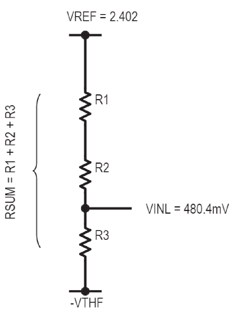
Figure 4. Falling Edge.
This gives us the following equation, assuming that the current is the same.

Which gives us the equation for R3:

With these three equations we can compute the values for R1, R2 and R3.
Design Example
Using the ideas which we discussed earlier, let’s design the ±24V application in Figure 1. We define –23.5V and –22.4V as the rising and falling thresholds respectively.
The goal is to minimize current draw through the resistors, yet still maintain reasonable accuracy. To minimize total supply current, the largest possible resistor value is used. The largest common 1% resistor value being 3.32MΩ, it is used to set R3. Then the values of R2 and R1 can be calculated using equations (1), (2) and (3). For a 24V application with rising and falling negative thresholds of –23.5V and –22.4V respectively, we get the following 1% resistor values.
R1 = 11.8kΩ
R2 = 267kΩ
R3 = 3.32MΩ
The divider current is 7µA, which is consistent with our goal of low current consumption while at the same time minimizing errors arising from INHB and INLB bias currents which can be up to 1nA each.
These tedious calculations can be avoided with the help of an excel based resistor calculator tool which computes the 1% resistor values for desired rising and falling thresholds. Click here to download the tool.


