


製品概要
設計リソース
設計/統合ファイル
- Schematic
- PCB Layout
- PCB CAD files
- PCB Gerber files
- BOM
- STM32F4 Platform
評価用ボード
型番に"Z"が付いているものは、RoHS対応製品です。 本回路の評価には以下の評価用ボードが必要です。
- MAXREFDES60# EV Kit
説明
Industry 4.01 marks the fourth industrial revolution, characterized by distributed, intelligent control systems. Breaking from a past with large, centralized programmable-logic controllers, Industry 4.0 allows for highly configurable, highly modular factories to provide analog signal controls to numerous equipment and operate at a higher output than ever before. The ultra-small PLC, or Micro PLC, lies at the heart of the Industry 4.0 factory, providing high performance with ultra-low power consumption in an ultra-small package. The MAXREFDES60# is Analog Devices’ Micro PLC analog output card.
The MAXREFDES60# features a 16-bit, high-accuracy 0V–10V analog output with isolated power and data. The MAXREFDES60# design integrates a low-noise, fast-settling buffer (MAX9632); a 16-bit, low-power DAC (MAX5216); an ultra-high precision 4.096V voltage reference (MAX6126); 600VRMS data isolation (MAX14850); a STMicroelectronics® STM32F4 microcontroller; an FTDI USB-UART bridge; a high-efficiency DC-DC converter (MAX17552); and isolated/regulated +15V, +5.5V, and -3V power rails (MAX17498C/MAX8719/MAX1659/MAX1735). The entire system typically operates at less than 250mW and fits into a space roughly the size of a credit card. While targeted for industrial Micro PLC applications, the MAXREFDES60# can be used in any application that requires high-accuracy analog output.
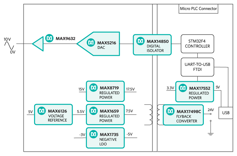
Figure 1. The MAXREFDES60# reference design block diagram.
機能と利点
- High accuracy
- 0 to 10V voltage output with ±20% overrange
- Isolated power and data
- Micro PLC form factor
- Device drivers
- Example C source code
- Test data
詳細
Industry 4.01 marks the fourth industrial revolution, characterized by distributed, intelligent control systems. Breaking from a past with large, centralized programmable-logic controllers, Industry 4.0 allows for highly configurable, highly modular factories to provide analog signal controls to numerous equipment and operate at a higher output than ever before. The ultra-small PLC, or Micro PLC, lies at the heart of the Industry 4.0 factory, providing high performance with ultra-low power consumption in an ultra-small package. The MAXREFDES60# is Maxim’s Micro PLC analog output card.
The MAXREFDES60# features a 16-bit, high-accuracy 0V–10V analog output with isolated power and data. The MAXREFDES60# design integrates a low-noise, fast-settling buffer (MAX9632); a 16-bit, low-power DAC (MAX5216); an ultra-high precision 4.096V voltage reference (MAX6126); 600VRMS data isolation (MAX14850); a STMicroelectronics® STM32F4 microcontroller; an FTDI USB-UART bridge; a high-efficiency DC-DC converter (MAX17552); and isolated/regulated +15V, +5.5V, and -3V power rails (MAX17498C/MAX8719/MAX1659/MAX1735). The entire system typically operates at less than 250mW and fits into a space roughly the size of a credit card. While targeted for industrial Micro PLC applications, the MAXREFDES60# can be used in any application that requires high-accuracy analog output.
Figure 1. The MAXREFDES60# reference design block diagram.
The power requirement is shown in Table 1.
| Power Type | Input Voltage (V) | Input Current (mA, typ) |
| On-board isolated power | 24 | 10 |
Note: STM32 and FTDI are powered by USB separately.
The analog output circuit consists of a 16-bit, rail-to-rail DAC MAX5216 (U401) and a low-noise fast-settling operational amplifier MAX9632 (U403). The DAC’s reference input is driven by an ultra-high precision 5V voltage reference, the MAX6126 (U402), with 0.02% initial accuracy and a 3ppm/°C maximum temperature coefficient (tempco). The output of the DAC is 0V to 5V, and the op amp amplifies the signal to 0V to 10V plus 20% margin.
The MAXREFDES60# uses the ultra-efficient MAX17498C (U501) to generate the isolated +17.5V, +7.5V, and -5V rails from a 24V supply. The MAX8719 (U102), MAX1659 (U103), and MAX1735 (U104) provide post-regulated +15V, +5.5V, and -3V rails. The MAX14850 (U301) digital data isolators provide data isolation. The combined power and data isolation achieved is 600VRMS.
The MAX17552 (U101) step-down DC-DC converter converts the +5V supply from the USB to +3.3V and powers the STM32 (U1) microcontroller and FTDI (U201) USB-UART bridge.
The equation to convert the DAC code to output voltage is:
VOUT = 12 × CODEDAC/65536
Detailed Description of Firmware
The MAXREFDES60# uses the on-board STM32F4 microcontroller to communicate with the DAC.The user sets the DAC output code through a terminal program.The user can also use the MAXREFDES60# to generate a customized sine wave. The simple process flow is shown in Figure 2. The firmware is written in C using the Keil® µVision® 5 tool.

Figure 2. The MAXREFDES60# firmware flowchart.
The firmware accepts commands, writes statuses, and is capable of generating a user-customized sine wave. The complete source code is provided to speed up customer development. Code documentation can be found in the corresponding firmware platform files.
Equipment used:
- Maxim custom FPGA test board
- Agilent® 3458A digital multimeter
- Agilent E3631A DC power supply
- National Instruments® GPIB card and cable
- Perl script for controlling the FPGA development kit and measurement equipment
- Windows PC
- MAXREFDES60# board
Measurements of DNL, INL, and TUE for the 0V to 10V voltage output with a 20% overrange are shown in Figure 4, Figure 5, and Figure 6, respectively.
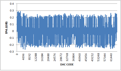
Figure 4. DNL for 0V to 10V output with 20% overrange.
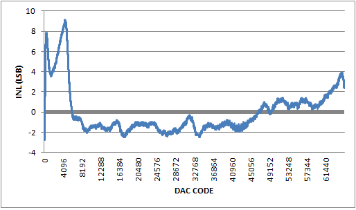
Figure 5. INL for 0V to 10V output with 20% overrange.
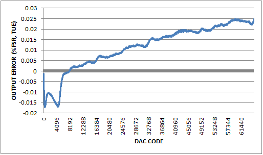
Figure 6. Output error for 0V to 10V output with 20% overrange.
Reference
1 The new generation of manufacturing production is called Industry 4.0 in Germany and Smart Manufacturing System elsewhere. See, Securing the future of German manufacturing industry, Recommendations for implementing the strategic initiative INDUSTRIE 4.0, Final report of the Industrie 4.0 Working Group, Industry 4.0 Working Group, Acatech National Academy of Science and Engineering, April 2013, https://www.acatech.de/wp-content/uploads/2018/03/Final_report__Industrie_4.0_accessible.pdf. Henceforth cited as Industrie 4.0. Although the Industrie 4.0 report is focused on Germany, the implications of the German research and findings are recognized for industry in other countries. See also Ferber, Stefan, “Industry 4.0 – Germany takes the first steps toward the next industrial revolution,” Bosch Software Group, Blogging the Internet of Things, October 16, 2013.
There are many sources for Smart Manufacturing Leadership. An interesting summary report of issues and topics can be found at the Smart Manufacturing Leadership Coalition Committee Working Meeting, Minneapolis, MN, U.S., Thursday, October 20, 2011, https://smart-process-manufacturing.ucla.edu/workshops/2011-workshop/presentations/SMLC%2010-20-11v3.pdf. Also see, Implementing 21st Century Smart Manufacturing, Workshop Summary Report, Smart Manufacturing Leadership Coalition, June 24, 2011, https://smart-process-manufacturing.ucla.edu/about/news/Smart%20Manufacturing%206_24_11.pdf. A simple web search on the topic will reveal considerably more references.
µVision is a registered trademark of ARM, Inc.
Agilent is a registered trademark and registered service mark of Agilent Technologies, Inc.
Keil is a registered trademark and registered service mark of ARM Limited.
National Instruments is a registered trademark of National Instruments Corporation.
STMicroelectronics is a registered trademark of STMicroelectronics, Inc.
Windows is a registered trademark and registered service mark of Microsoft Corporation.
Required equipment:
- Windows® PC with a USB port
- MAXREFDES60# board
- 24V power supply
- Voltmeter
Procedure
The reference design is fully assembled and tested. Follow the steps below to verify board operation:
- Turn or keep off the 24V power supply.
- The MAXREFDES60# utilizes the FTDI USB-UART bridge IC. If Windows cannot automatically install the driver for the FTDI USB-UART bridge IC, the driver is available for download from www.ftdichip.com/Drivers/VCP.htm.
- Connect the negative terminal of the 24V power supply to the PGND connector on the MAXREFDES60# board. Connect the positive terminal of the 24V power supply to the +24V connector on the MAXREFDES60# board.
- Turn on the 24V power supply.
- Connect the USB cable from the PC to the MAXREFDES60# board.
- Open the hyperterminal or similar terminal program on the PC. Find the appropriate COM port, usually a higher number port, such as COM4 or COM6, and configure the connection for 921600, n, 8, 1, none (flow control).
- The MAXREFDES60# software displays a menu (Figure 3).
- For immediate signal testing, connect the negative terminal of the voltmeter to the GND terminal of the P401 terminal block. Connect the positive terminal of the voltmeter to the OUT terminal of the P401 terminal block. The outputs are labeled on the bottom side of the board.
- Press 1 in the terminal program to select Set DAC output.
- Type in 7FFF and press the Enter key.
- Verify the output voltage is approximately 6V.

Figure 3. Terminal program main menu.
関連資料
-
MAXREFDES60 Design Files2021/02/17ZIP10 M
サポートおよびトレーニング
技術的なご質問についての回答は、ナレッジベースを検索してください。また、アナログ・デバイセズのアプリケーション・エンジニアの専任チームが、技術的なご質問にお答えいたします。