製品概要
機能と利点
- Features LTC4306, a 4-channel, 2-wire I2C bus and SMBus compatible multiplexer having bus buffers that provide capacitive isolation between the upstream bus and downstream buses
- 6-pin PMOD connectors for upstream and downstream connection for compatibility with PMOD form factors such as EVAL-ADICUP3029 (Arduino based Wireless Development Platform based on an ultra-low power ARM Cortex-M3 processor) or with EVAL-SDP-CK1Z (SDP-K1 Cortex ARM core processors Controller Board and color sensor)
製品概要
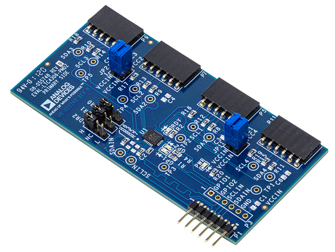
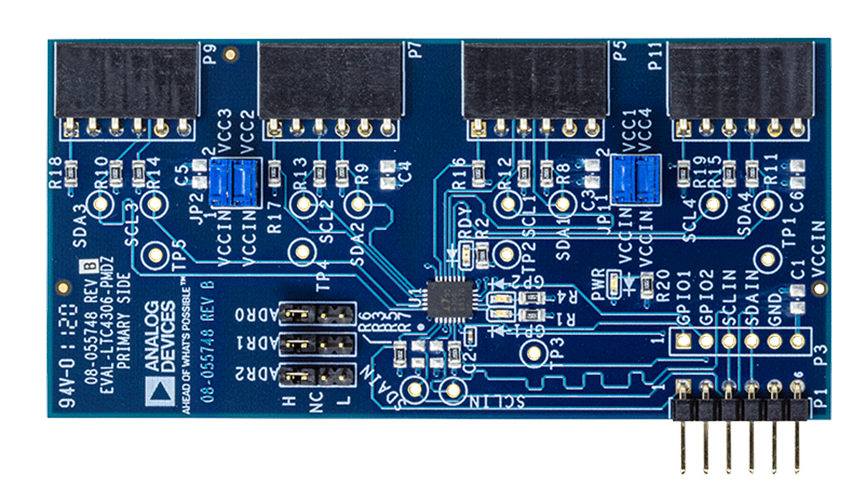
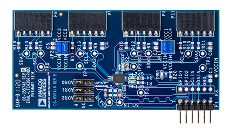
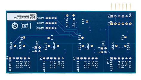
The EVAL-LTC4306-PMDZ features LTC4306, a 4-channel, 2-wire I2C bus and SMBus compatible multiplexer having bus buffers that provide capacitive isolation between the upstream bus and downstream buses. This evaluation board provides 6-pin PMOD connectors for upstream and downstream connection for compatibility with PMOD form factors such as EVAL-ADICUP3029, an Arduino based Wireless Development Platform for Internet of Things applications based on an ultra-low power ARM Cortex-M3 processor.
Pmod™ is the Digilent defined standard of Peripheral Modules, small I/O interface boards that offer an ideal way to extend the capabilities of programmable logic and microcontroller boards. They allow sensitive signal conditioning circuits and high-power drive circuits to be placed where they are most effective — near sensors and actuators.
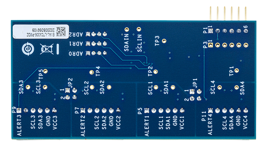
EVAL-LTC4306-PMDZ comes with PMOD connectors on both upstream and downstream side for compatibility with PMOD form factors, 10K pull up resistors on upstream and all downstream buses and 0.1uF bypass capacitor on the upstream side. The user has the option to add 6 pin 2.54mm pitch pin header for connection to the GPIOs (General Purpose Input/Output pins) on EVAL-LTC4306-PMDZ for extra functionality. The user also has the option to add test points on different places on the board for fault monitoring and place additional bypass capacitors (0805 size footprint) on the upstream and the downstream side for defense against any unwanted noise in their system for adequate bypassing on power supply lines.
はじめに
Please see the EVAL-LTC4306-PMDZ User Guide for complete details.
EVAL-LTC4306-PMDZ is easy to set up to evaluate the performance of the LTC4306. Refer to Figure 1 of the user guide for proper measurement equipment setup and follow the procedure below:
- Power up the upstream side of the board and the LTC4306 via the P1.6 pin. Connect P1.5 to GND and P1.4 and P1.3 to SDA and SCL of the host controller respectively. If the host controller is available in a PMOD form factor, plug in the P1 PMOD connector into the six pin PMOD host connector of the controller.
- Power up the downstream buses 1-4 using separate power supplies or from the upstream side. To power all the buses using the upstream voltage supply, place both the jumper JP1 and JP2 in A and B positions. This will connect VCCIN to the VCC1-VCC4 of the downstream buses.
- Configure jumpers JP6 – JP8 to set the desired 2- wire bus address for the LTC4306 according to Table 1 on page 13 of the datasheet (note: left position = L, middle position = NC, right position = H; Disconnect = NC for all three jumpers). By default, the address 0xAA is selected.
- Connect the SCLx and SDAx of the desired downstream bus to the SCL and SDA pin of the peripheral/slave device.
- To close all the FET switches to enable communication to all the downstream buses, send in a SMBus write command to change each of the bit 4,5,6 and 7 on register 3 on the LTC4306 to 1.
- Now any slave on any of the downstream bus 1-4 can be addressed seamlessly with the data transparently transmitted from the controller to the peripheral/slave devices.
- To experiment with more features of LTC4306, use the SMBus Read Byte and Write Byte protocols in conjunction with the register definitions on pages 8 and 9 of the datasheet.
推奨システム動作環境
Controller
Peripheral
Power
Hardware Required for Demo with ADICUP3029 and a Digital Sensor
- EVAL-LTC4306-PMDZ board
- EVAL-ADICUP3029 Evaluation board
- EVAL-ADT7420-PMDZ Digital Temperature sensor Evaluation board
- SDP-K1 controller board (Optional)
- Mirco USB to USB cable
- Windows® Vista 32-bit/64-bit, Windows 7 32-bit/64-bit, Windows 8 32-bit/64-bit, or Windows 10 32-bit/64-bit with USB 2.0 port
Hardware Required for Demo with EVAL-SDP-CK1Z and a Color Sensor
- SDP-K1 controller board
- EVAL-LTC4306-PMDZ board
- I2C Color sensor/RGB sensor (For this example, TC347525 from Adafruit industries was used)
- 2 m, USB standard-A to mini-B cable
- Windows® Vista 32-bit/64-bit, Windows 7 32-bit/64-bit, Windows 8 32-bit/64-bit, or Windows 10 32-bit/64-bit with USB 2.0 port
- Jumper wires to connect different boards together
関連資料
-
EVAL-LTC4306-PMDZ User Guide2021/12/22WIKI
