製品概要
機能と利点
- Input voltage: 4.5 V to 20 V
- ±1% output voltage accuracy
- Integrated 48 mΩ typical on-resistance high-side MOSFET
- Flexible output configuration
Dual output: 5 A/5 A
Parallel single output: 10 A - Programmable switching frequency: 250 kHz to 1.2 MHz
- External synchronization input with programmable phase shift, or internal clock output
- Selectable PWM or PFM mode operation
- Adjustable current limit for small inductor
- External compensation and soft start
- Startup into precharged output
製品概要
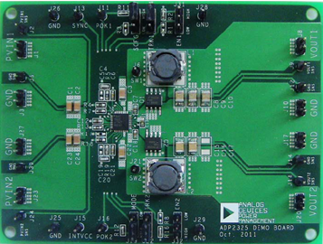
The ADP2325 evaluation board, ADP2325-EVALZ, is a complete, dual, 5 A step-down regulator solution that allows users to evaluate the performance of the ADP2325 with a near ideal printed circuit board (PCB) layout.
The two pulse-width modulation (PWM) channels can be configured to deliver dual, 5 A outputs or a parallel-to-single, 10 A output. The switching frequency can be programmed between 250 kHz and 1.2 MHz, or it can be synchronized to an external clock with a programmed 60°, 90°, or 120° phase shift, which provides the possibility for a stackable multiphase power solution.
The outputs of the ADP2325 evaluation board are preset to 1.2 V and 3.3 V for Channel 1 and Channel 2, respectively. With the PWM mode selected, the switching frequency is set to 500 kHz. Different output voltage settings and configurations can be achieved by changing appropriate passive components or jumper settings. The ambient temperature operating range is −40°C to +85°C.
Full details on the ADP2325 dual regulator are provided in the ADP2325 data sheet, available from Analog Devices, Inc., which should be consulted in conjunction with this user guide.

