Tiny Voltage Converter Boosts a Single Lithium Cell and Needs no Inductors
要約
In this design note a battery voltage is boosted by a charge-pump voltage doubler, the MAX1683, and stepped down to the desired level by a micropower linear regulator, the MAX1615. A single-cell regulator circuit maintains a 5V output without inductors.
A similar version of this article appeared in the October 4, 1999 issue of EE Times magazine.
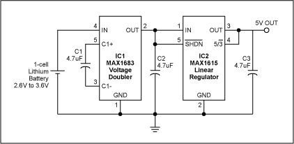
Switched-capacitor charge pumps, which offer a size advantage over the equivalent inductor-based regulator, are popular for boosting the battery voltage in small handheld equipment. As an example, the subscriber identification module (SIM) in European cellular phones requires a regulated 5V for powering low-current loads. One such circuit (Figure 1) employs two tiny SOT-23 ICs and three surface-mount capacitors to double and post-regulate the voltage of a single Li+ battery. It delivers 15mA from a 2.7V minimum output voltage.

Figure 1. This 1-cell regulator circuit maintains a 5V output without the use of inductors.
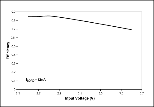
Battery voltage is boosted by a charge-pump voltage doubler with 2V–5.5V input range (IC1), and stepped down to the desired level by a micropower linear regulator (IC2). As the battery discharges, the system compensates declining voltage with an increase in efficiency, reaching 84% at 2.8V (Figure 2). Because the SIM and other smart cards are used only a few times a day and for less than a second each time, one can sacrifice some efficiency for smaller size and lower cost. The circuit's low quiescent current ranges from 60µA at 2.6V to 80µA at 3.6V.

Figure 2. Efficiency for the Figure 2 circuit improves as the battery discharges.