Step-Up/Step-Down Converter Features Ultra-Low Quiescent Current
要約
This design is intended to be used in portable applications where the input power source is provided by three NiCd or NiMH cells (3.6V without load) and where the output voltage is 3V. When the input battery is fully charged, the input voltage is above 3V and when the power source is half or near fully discharged, the input voltage is below 3V.
A 3V, 100mA regulated output is generated with a typical quiescent current below 12µA. Input voltage ranges from 2V to 5V and power conversion efficiency is above 60%. It consists of a step-up converter (U1: MAX1833) followed by a LDO (U2: MAX8880). It offers a POK output signal that can be used as µP reset signal, and integrated reverse input battery protection.
To reduce power consumption, some applications need to be cycled between active and sleep modes. In sleep mode, the quiescent current of the system is dominated by the power supply. Current must be as low as possible because it is impossible to turn off the power supply, as it must remain active to supply some parts of the system.
This design is intended to be used in portable applications where the input power source is provided by three NiCd or NiMH cells (≈ 3.6V without load) and where the output voltage is 3V. When the input battery is fully charged, the input voltage is above 3V and when the power source is half or near fully discharged, the input voltage is below 3V.
Some solutions already exist:
- Step-up converter in a SEPIC configuration
- Step-up + LDO such as MAX1672
- Charge pump such as MAX1759
All these solutions have quiescent currents in the 100µA range (MAX1672: 125µA; MAX1759: 180µA). In sleep mode, this is too much for some portable applications.
This design generates a 3V, 100µA regulated output voltage power supply with a typical quiescent current below 12µA. Input voltage ranges from 2V to 5V and power conversion efficiency is above 60%. It consists of a step-up converter (U1: MAX1833) followed by a LDO (U2: MAX8880). It offers a POK output signal that can be used as µP reset signal, and integrated reverse input battery protection.

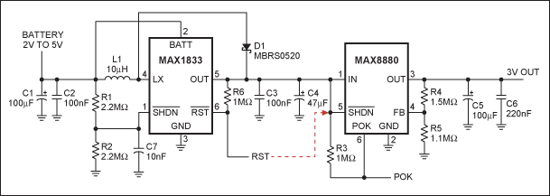
Figure 1.
Detailed Description
When the voltage at the cathode of D1 is above the limit defined by the desired output voltage (3.3V in this case), the MAX1833 does not switch and quiescent current is typically 5µA. The system behaves as a classic LDO with a typical 5µA quiescent current (including bias current in the feedback divider R4/R5). The overall quiescent current is below 10µA typ. 5µA is drawn by U1 and 5µA is drawn by U2.
When the voltage at the cathode of D1 is under the limit defined by the desired output voltage (3.3V in this case), the step-up powers-up in PFM mode with a constant ON time. The switching frequency is a function of the load current. In sleep mode, the load current is only a few µA. Switching frequency is very low (about 10Hz). Quiescent current is below 12µA (typ) 7µA is from U1 and 5µA (max) is from U2.
When the system wakes up, the load begins to draw current. Response time is fast (because of the LDO).
Accuracy of the threshold voltage at SHDN input is 1.228V ±3.5% so a complete shutdown function occurs when input voltage is too low. In this example, we have a divide by 2, which means that when the battery voltage is under about 2.46V, the step-up is in real shutdown mode (IQ < 1µA) and if its RST output is directly connected to SHDN of the MAX8880 (as shown in red dotted line), the LDO enters into real shutdown mode (IQ < 1µA) and the output voltage is 0V.