Flexible Hot-Swap Current Limiter Allows Thermal Protection
要約
Application note describes a flexible current limiting circuit employing a hot-swap controller with external MOSFET. Circuit features settable current limit and optional thermal protection via thermistor feedback.
Current limiting is often necessary to protect a power supply from short circuits and surges, which can affect operation by pulling the supply voltage low. ICs containing a p-channel MOSFET and an adjustable current limit are available for this purpose, but most are restricted to 5V systems with a typical maximum-current limit of 2A and with low accuracy (20% to 50%, according to the manufacturers).
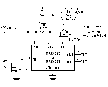
The current-regulation capability of a "hot-swap controller" (IC1 in Figure 1) makes possible a current limiter that is more accurate and versatile. The external MOSFET and sense resistor enable this device to protect a system operating on 3V to 12V. Connecting the CTIM terminal to ground disables the IC's DualSpeed/Bilevel feature, thereby forcing the device into startup mode, which regulates the current at the limit pre-set by the sense resistor (ILIM = 200mV / RSENSE).

Figure 1. Combining these external components with a hot-swap-controller IC provides a precision current-limited supply for a 3V-to-12V load.
Achievable accuracy is 10% not including the sense-resistor error, which is a great improvement over the approach mentioned above. The circuit not only protects against short circuits and current surges, but it also limits the inrush current and ramps the supply voltage by restricting the MOSFET's gate-charging current to 100µA. Driving the ON terminal (pin 8) to ground disconnects the load.
The external MOSFET easily handles normal operation; however, a short circuit elevates its power dissipation and die temperature by imposing the full supply voltage across the MOSFET and the sense resistor. Thermal protection is necessary if this condition holds for an extended period.
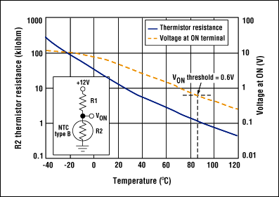
You can add thermal protection by placing an NTC temperature monitor close to the MOSFET (on the back side of the board) and using the precision comparator internal to IC1 (accessible at the ON terminal) to disconnect the load when this monitor detects excessive temperature. The components shown, for example, provide a temperature threshold of 85°C when VCCIN = 12V, R1 = 20kΩ, and the type-B thermistor (R2) = 10kΩ at 25°C (Figure 2).

Figure 2. The NTC thermistor resistance, in Figure 1, varies with temperature, as shown.