Configure the Charge and Discharge Current Separately in MAX38888
要約
The design of a front-end converter can be made less complicated when minimal extra current overhead is required for charging the supercapacitor. This application note explains how to configure the reversible buck/boost converter to achieve a lighter impact on the system during the charging phase. Setting the charge current requirement to the minimum amount keeps the discharge current availability intact.
Introduction
Rapid advancements in the field of low power, portable, and battery-powered equipment demand robust and versatile backup solutions to keep systems up and running without any interruptions.
To avoid high current discharge periods, it is advisable to drain the main source at a lower rate, especially during the initial state of the operation when it usually engages in waking up the main system units. One way to achieve this is to disable the super cap charging during normal operation and enable the charging while the system is in sleep mode. Another way is to limit the charging current to a lower level from the beginning of the operation, so that the main system operation is not affected by the MAX38888 operation. In this way, the battery would not experience high discharge rate periods and efficiency can be improved.
The MAX38888 is a highly integrated, single-cell, highly efficient supercapacitor (SCAP) backup solution in the Continua family of devices. It has resistor selectable voltage and charge/discharge current settings. It uses a single resistor to set both charge and discharge current options. This application note aims to demonstrate and expand the use of the MAX38888 to achieve myriads of application where it demands different settings for charge/discharge currents.
Operation of the MAX38888
Maxim's MAX38888 reversible buck/boost regulator is in the Continua™ family of backup power regulators, using a supercapacitor or capacitor bank. The MAX38888 is designed to efficiently transfer power between a storage element and a system supply rail. When the main battery is present and above the minimum system supply voltage, the regulator operates in buck mode and charges the storage element up to a 500mA rate. Once the storage element is charged, the circuit draws only 2.5µA of current while it maintains the supercapacitor or other storage element in its ready state. When the main supply is removed, the regulator operates in boost mode and prevents the system from dropping below the minimum operating voltage, discharging the storage element at up to a 2.5A rate. The MAX38888 is externally programmable for minimum and maximum voltage of the storage element, such as the SCAP, minimum system voltage, and maximum charge and discharge currents. The peak inductor discharge current is set by placing a resistor from ISET to GND. The values of RISET resistor are calculated by the following formula:
Discharge current = 
The supercapacitor charging current is internally set to 1/5 of the discharge current.
Charge current = 
The value of RISET between 20kO and 100kO is recommended to ensure accurate current compliance.
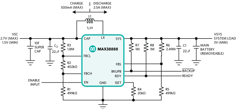
Figure 1. Typical application diagram of MAX38888 with proportional charge/discharge current settings.
Features of the MAX38888 include:
- 2.5V to 5V system output voltage
- 0.8V to 4.5V cap voltage range
- Up to 2.5A peak inductor discharge current
- Programmable voltage and current thresholds
- ±2% threshold accuracy
- Up to 95% efficiency, charge, or discharge
- 2.5µA ready quiescent current
- Highly integrated and small solution size
- 3mm x 3mm x 0.75mm TDFN package
- Power Backup Applications
- Energy Storage Applications
Applications of this family of devices can be categorized into two types.
During battery replacements or when power outages or main power failures occur, this family of devices can be used for the auxiliary power supply units to either power the system during data backup or as a dying gasp. Other notable areas of application include camera, security tags, electronic, water and gas meters, smoke detectors, and remote controls.
This is used when the main power supply to the unit demands a storage unit to provide a regulated supply to the associated system, especially in the energy harvester applications.
The Need for Lower Super Cap Charge Current Configuration
In many short-range wireless sensor networks, although the average current consumption of a device is low, the instantaneous current can be high. For example, a transceiver with a sleep current of 1µA and a peak active current of 20 mA wakes up every two seconds and stays active for 5ms. The average current consumption is only 50µA, but the peak current is 20mA and can have an adverse effect on the battery's actual capacity, especially if there is not enough time between the periods of high current discharge to let the battery rest and recover.
When a battery is discharged at a high and sustained rate, the battery reaches its end of life, even if there are still active materials left in the battery. However, if the discharge rate is not continuous and there are cutoffs or very low-current periods, the transport rate of active materials catches up with the depletion of the materials, giving the battery a chance to recover the capacity lost at the high discharge rate. For a battery to be a viable option for a specific system, it must meet the system requirements for size, supply voltage, and average and maximum dynamic currents needed for the system to operate. Charging the storage devices used for the backup application should not harness the actual system power requirement.
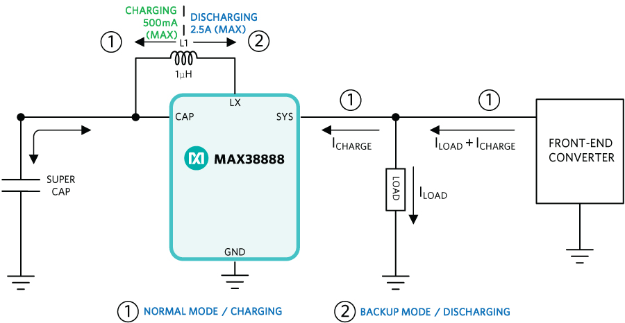
Figure 2. Demonstration of an application where a lower charge current setting is necessary.
Most of the systems require the charging current to be proportional to the discharge current. But there are some special limited energy applications where the system demands a lower charging current while keeping the discharge rate intact. For example, the SCAP charging current is set by the inductor peak current limit of 500mA, which corresponds to a higher discharge current requirement. In this case, the charging current would be around 250mA. In figure 2, the MAX38888 demands a higher charging current. In turn, an impact is made on the front-end converter, irrespective of the load. The main power supply is energy limited, especially during active operation of the complete system.
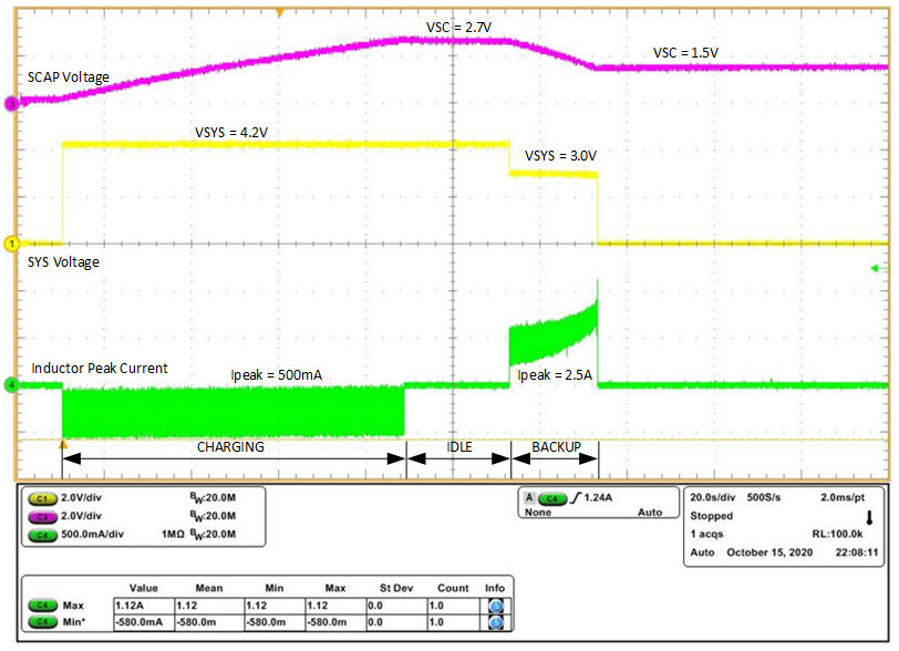
Figure 3. Bench result of charge and discharge profile of MAX38888 with proportional charge/discharge inductor current settings.
How to Configure the Charge and Discharge Current Separately
The table below represents an example of working the solution with specific conditions.
| Condition | Solution |
| Minimum SYS charge voltage for a backup voltage of 3.0V = 3.36V | Typical VSYS = 4.2V |
| SCAP full charge voltage = 2.7V | SCAP preserve mode minimum voltage = 1.5V |
| The maximum load in backup is ~500mA | SCAP minimum voltage = 1.5V |
| Peak inductor current in discharge/back-up phase | 2.5A |
| Peak inductor current in SCAP charge phase | 500mA (without additional circuitry) |
| Peak inductor current in SCAP charge phase | 100mA (with additional circuitry) |
| Regulated voltage during backup phase VSYS(BACKUP) | 3.0V |
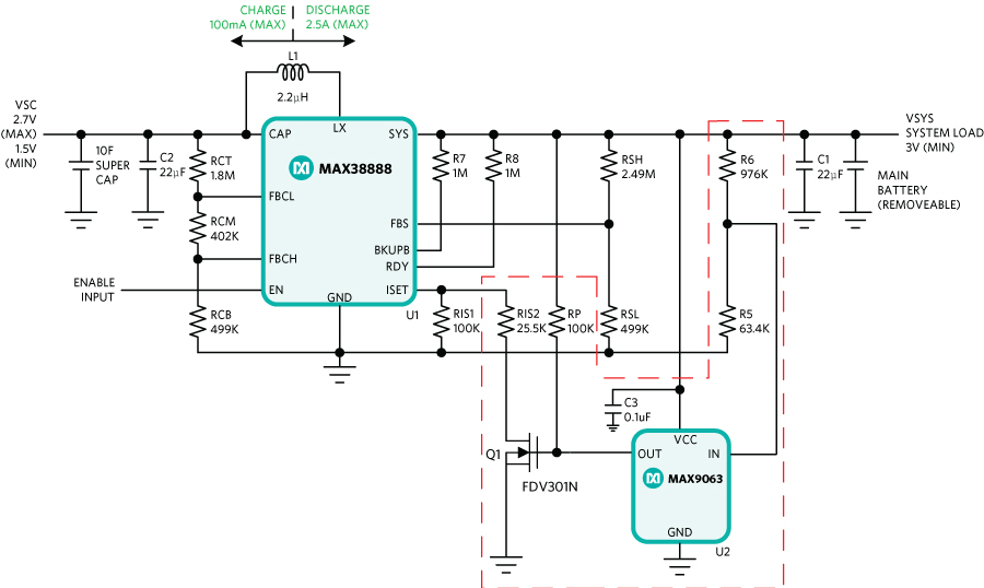
Figure 4. MAX38888 diagram with a modified circuit for different charge/discharge current settings.
The MAX9063 is used as part of an added circuitry to include the feature mentioned in this application. It is a nanoPower comparator with an integrated voltage reference of 200mA and is rated to consume only 40nA. The comparator trip points are configured using another voltage divider, R5, and R6 at the SYS pin side to activate an nMOS signal MOSFET based on the VSYS level.
For a regulated backup voltage of 3.0V, the charging of SCAP starts when the SYS voltage is above the 3.36V minimum. During the charging of the SCAP, comparator MAX9063 output is at logic LOW (VIN > 200mV). Hence, the Q1 (nMOS) is turned off, ensuring the effective RISET value is unchanged as 100K?. The result is the slowest charging inductor peak current configuration of ~100mA in buck mode of operation.
When the VSYS voltage falls below a discharge threshold voltage level, the IN voltage at the MAX9063 falls below 200mV and triggers the comparator output to logic HIGH, turning the Q1 on. The RIS2 is connected to the ground and acts as a parallel resistor to RIS1, changing the charge (boost mode) inductor peak current to the maximum possible with an effective RISET = 100K ||25K = 20K. This results in the highest inductor peak current configuration of ~2.5A during the discharge phase.
Design of the External Circuit to Configure the Charge and Discharge Current Separately
- Internal reference voltage of MAX9063 = 200mV
- Minimum SYS voltage needed to charge the SCAP for a 3.0V regulated output = 3.36V
- Set trip voltage for comparator to 3.3V
- Choose R6 = 976K?
- MAX9063 open-drain output is pulled up to SYS voltage with a 100K? pullup resistor.

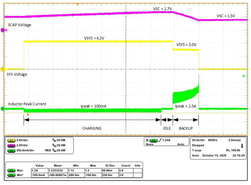
Figure 4. MAX38888 diagram with a modified circuit for different charge/discharge current settings.
Bill of Materials
| No. | Item | Qty. | Manufacturer PN | Manufacturer | Description |
| 1 | R6 | 1 | CRCW0603976KFKEA | Vishay Dale | SMD Resistor, 1%, 0.1W, 976kOhm, 0603, Thick film |
| 2 | R5 | 1 | CRCW060363K4FKEA | Vishay Dale | SMD Resistor, 1%, 0.1W, 63.4kOhm, 0603, Thick film |
| 3 | RIS2 | 1 | CRCW060325K5FKEA | Vishay Dale | SMD Resistor, 1%, 0.1W, 25.5kOhm, 0603, Thick film |
| 4 | RP | 1 | CRCW0603100KFKEA | Vishay Dale | SMD Resistor, 1%, 0.1W, 100kOhm, 0603, Thick film |
| 5 | C3 | 1 | C1608X7R1H104K080A | TDK | 0.1uF; 50V; 10%; Ceramic Capacitor; 0603; X7R |
| 6 | U2 | 1 | MAX9063EUK+ | Maxim Integrated | nanoPower Comparator with Reference, SOT23-5 |
| 7 | Q1 | 1 | FDV301N | On Semi | SMD Logic Level NMOS, 25VDS, 0.22A, SOT23-3. |
Conclusion
When the system source of an application is energy-limited or part of an energy harvester system, a slower SCAP charge current is necessary without relaxing on a load current requirement during the backup phase. The altered RISET resistor setting is supported during charge and backup mode through use of an added circuitry with external components. The Continua family of devices is flexible enough to support applications in low-power electronics primarily powered by batteries, such as remote sensors and embedded devices.