Adding Battery-Detection Functionality to the DS1312, DS1314, and DS1321 Controller ICs
要約
The DS1312, DS1314, and DS1321 are nonvolatile controller ICs that have a built-in battery-voltage monitor. The monitor measures the voltage of a lithium cell connected to the VBAT pin and issues a warning when the battery voltage is low. The battery voltage is measured once during power-up and once every 24 hours thereafter. As long as a battery is attached to the VBAT pin, the device operates properly. However, if the battery is removed and the VBAT pin is left floating, erroneous battery-voltage measurements might be made, depending on the value of the floating VBAT voltage. This application note describes how to add battery-detection functionality to the DS1312, DS1314, and DS1321 devices.
Battery-Voltage Monitor Description
The battery-voltage monitoring circuits of the DS1312, DS1314, and DS1321 were designed to measure the voltage of a lithium cell attached to the VBAT pin. The intent was that a battery would always be connected to the VBAT pin, except for a short battery-replacement period. Once during power-up and once every 24 hours after power-up, an internal 1.2Mohm resistor is used to measure the voltage of the lithium cell connected to the VBAT pin. If no battery was attached to the VBAT pin during power-up, then the battery warning pin, /BW, will be enabled as expected when VCCI rises above VCCTP. If, however, a battery was present during power-up and the initial battery voltage test, then later removed leaving the VBAT pin floating, the next battery-voltage test 24 hours later might not detect a voltage below VBTP on the VBAT pin. Thus, no battery warning would be activated even though the battery had been removed.
Battery-Presence Detection Circuit
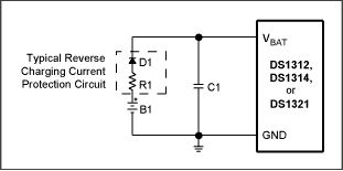
Battery-detection functionality can be added by connecting a small (0.1µF to 1nF) capacitor from the VBAT pin to ground. (See Figure 1 for the placement of the capacitor, C1.) The capacitor prevents the internal voltage oscillation on the VBAT pin caused by the removal of the lithium battery. By adding this capacitive load to the VBAT pin, the internal voltage oscillations on the VBAT pin are dampened, and the battery-voltage measuring circuit is then able to properly load the VBAT pin and discharge the voltage below VBTP, thus causing the low-battery warning alarm to become enabled and setting the /BW pin high.
If an application using the DS1312, DS1314, or DS1321 will always have a voltage source connected to the VBAT pin, whether that source is a lithium battery, other voltage source, or even a connection to ground, then this addition of the detection circuit is not necessary. Connecting the capacitor to the VBAT pin adds additional leakage and shortens the life of the battery (depending on the size of the battery and capacitor chosen), and also introduces the issue of having to protect that battery from reverse charging current.

Figure 1. Battery-Presence Detection Circuit
Protection-Circuitry Consideration
Adding a capacitor in parallel with the lithium battery requires additional components to protect the lithium cell from reverse charging current. When the DS1312, DS1314, and DS1321 leave battery backup mode, the VBAT pin becomes a high-impedance input. Because only the lithium battery and capacitor are connected to VBAT, there is an opportunity for the capacitor to reverse charge into the lithium cell, creating the need for the reverse charging current protection circuitry. Battery manufacturers recommend reverse charging current protection circuits so their products can meet UL conditions of acceptability. It is suggested that the engineer refer to the battery manufacturer's recommended reverse charging current protection circuit for that manufacturer's products. Typically, such a protection circuit consists of a resistor and diode (typically silicon) in series between the battery and any other connections. Figure 1 shows a typical reverse charging current protection circuit. The diode allows the battery to supply current to the application, but prevents current from feeding from the capacitor back into the battery. The resistor is in place to protect the battery in case the diode should fail, and to dampen any incoming current.
Conclusion
The DS1312, DS1314, and DS1321 nonvolatile controllers offer a low-battery warning function by means of a battery-voltage measurement circuit. When the connection to the VBAT pin is floating, the device has difficulty determining what voltage is present. The internal 1.2Mohm resistor on its own may not be enough to pull that unknown value below the VBAT trip point, VBTP. Adding a small capacitor to the VBAT pin provides enough load to allow the built-in battery measurement circuit to draw the floating voltage below VBTP and detect that there is no battery present.
Questions/comments/suggestions concerning this application note can be sent to: .