AN-1528: Using the AD7150 Capacitance-to-Digital Converter for Proximity Sensing Applications
Circuit Function and Benefits
The circuit described in this document provides the basis for developing a proximity sensing application using the AD7150 capacitance-to-digital converter (CDC).

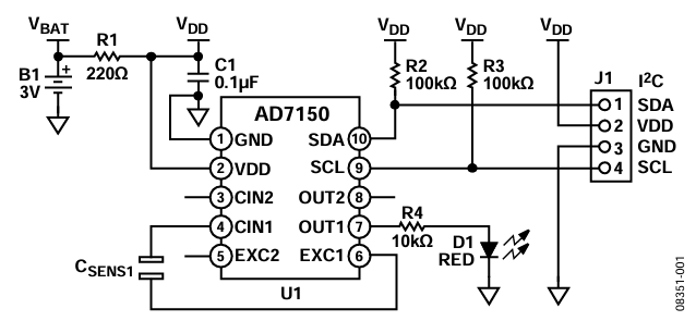
Figure 1. AD7150 as a proximity detector in standalone operation.
The AD7150 CDC measures the capacitance between two electrodes and compares the measurement result with a threshold value, which can either be fixed or dynamically adjusted by the on-chip, adaptive threshold algorithm engine.
If the input capacitance is altered, for example, by the presence of a hand, an output flag is set to indicate that a threshold has been exceeded, indicating proximity.
This on-chip, adaptive threshold algorithm engine also enables the AD7150 to adapt to slow changes in the sensing capacitance, which can be caused by environmental changes, such as humidity or temperature, without losing the capability of proximity sensing.
Circuit Description
A proximity sensing application using the AD7150 in standalone operation requires very few peripheral components, as shown in Figure 1. The circuit requires a supply voltage (Battery B1), some filtering of the supply voltage (R1, C1), and weak pull-up resistors (R2 and R3) on the I2C-compatible input/output pins. The red LED (D1) provides a visual indicator that the AD7150 has detected the proximity, for example, of a hand. The circuit requires a capacitive sensing element (CSENS1), which can consist of two tracks on an FR4 printed circuit board (PCB), as shown in Figure 2.

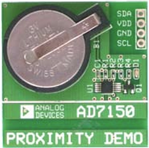
Figure 2. AD7150 proximity detector demonstration board.
Common Variations
Variations in the AD7150 proximity circuit depend on the environment and the targeted application. For example, automotive applications must withstand a high level of electromagnetic current (EMC) noise and transient pulses at the system level; therefore, this type of application requires a suitable design for harsh electrical and physical environments.
The unique design of the AD7150 for measuring floating capacitive sensors allows the user to place a filter structure in the capacitive front end. The filter structure (R1 to R6, C1 to C6), as shown in Figure 3, filters noise that is coupled into the electrodes of the sensor. The optional network consisting of R7, R8, C7, and C8 prevents noise from the external I2C-compatible interface from coupling back into the circuit.

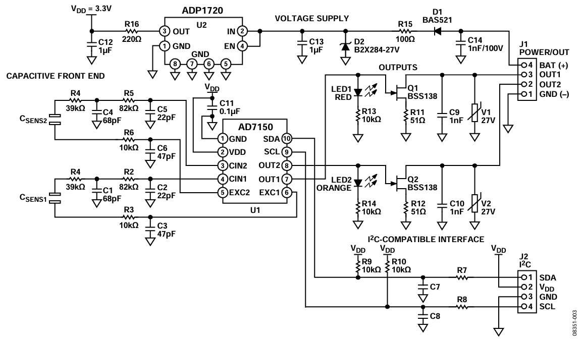
Figure 3. AD7150 in an automotive door handle application in standalone operation.
Substantial EMC testing has been performed on the AD7150. The results of the AD7150 EMC performance can be found in the AN-1011 Application Note, EMC Protection of the AD7150.
The excitation voltages (EXC1 and EXC2), which drive the capacitive sensors, are generated by circuits within the AD7150. The VDD pin powers these circuits. A noisy supply voltage can result in unwanted noise signals on the capacitive input. The voltage supply circuit shown in Figure 3 uses the ADP1720 low dropout (LDO) regulator, used in 3.3 V mode, to filter battery noise and suppress transient pulses in automotive applications.
If the outputs of the AD7150 are not connected directly to a microcontroller, they can require conditioning to translate the voltage level and/or signal polarity. Typical conditioning circuits for the OUT1 and OUT2 pins are shown in Figure 3. The double diffused metal-oxide semiconductor (DMOS) field effect transistors (FETs), Q1 and Q2, act as open drain output drivers, and the 27 V varistors (V1 and V2) protect the circuitry from large external transients.
When connected to a microcontroller, some of the AD7150 registers used by the on-chip adaptive threshold algorithm engine can be programmed to settings other than the power-up default settings. This programming is done via the I2C-compatible interface and enables the AD7150 to be used for different applications with different requirements. See the AD7150 data sheet for more details.
Table 1 and Table 2 show a typical proximity performance of the door handle demonstration with different sensitivity and capacitive input range settings.
| Capacitive Range (pF) | Threshold Sensitivity Setting | Maximum Proximity Detection (mm) |
| 0.5 | 4 | 38 |
| 8 | 31 | |
| 12 | 27 | |
| 16 | 24 | |
| 2.0 | 4 | 25 |
| 8 | 17 | |
| 12 | 12 | |
| 16 | 10 |

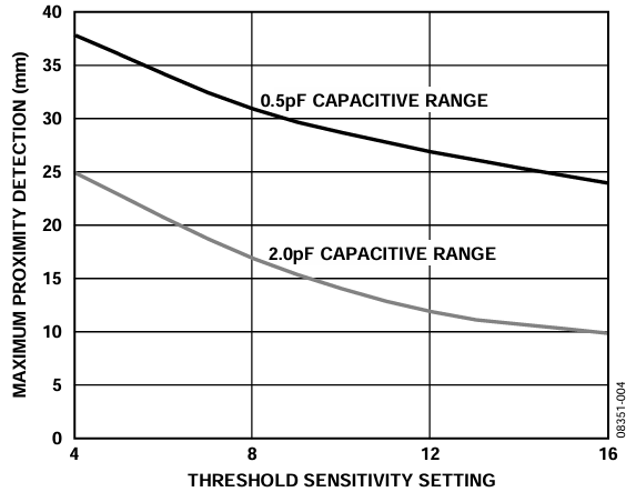
Figure 4. Typical proximity performance, sensor 1.
| Capacitive Range (pF) | Threshold Sensitivity Setting | Maximum Proximity Detection (mm) |
| 0.5 | 4 | 70 |
| 8 | 58 | |
| 12 | 50 | |
| 16 | 45 | |
| 2.0 | 4 | 45 |
| 8 | 35 | |
| 12 | 28 | |
| 16 | 24 |

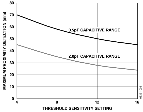
Figure 5. Typical proximity performance, sensor 2.
The unique design of the AD7150 for measuring floating capacitive sensors makes the AD7150 tolerant of parasitic capacitances to ground. This tolerance allows the use of ground planes to either shield the capacitive front-end signals from other analog or digital signals on the board, or to shield the signals from each other. Figure 6 shows the AD7150 door handle demonstration board where Sensor 2 on the door handle demonstration board has a ground plane on the entire top layer to prevent proximity detection when a person leans against the door handle of a car. The sensor electrodes are placed on the bottom layer in the same way as shown for Sensor 1 (see Figure 6). Therefore, Sensor 2 only detects proximity when a hand reaches behind the door handle.

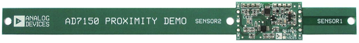
Figure 6. AD7150 door handle demonstration board.
References
AN-856 Application Note, AD7142 Applications Using Sensor Buttons, Analog Devices, Inc.
AN-925 Application Note, Sensors for the AD7147 and AD7148 CapTouch Controllers, Analog Devices.
AN-1011 Application Note, EMC Protection of the AD7150, Analog Devices.
MT-022 Tutorial, ADC Architectures III: Sigma-Delta ADC Basics, Analog Devices.
MT-031 Tutorial, Grounding Data Converters and Solving the Mystery of AGND and DGND, Analog Devices.