AN-1152: Calibrating a Single-Phase Energy Meter Based on the ADE7816
Introduction
This application note describes how to calibrate the ADE7816. It details the calibration procedure, including equations and examples of how to calculate each constant.
The ADE7816 is a high accuracy multichannel metering IC that allows the energy to be measured on up to six current channels.
It provides a variety of energy measurements including active and reactive energy, along with current and voltage rms readings. A variety of power quality features, including no load, reverse power, and angle measurement, are also provided. The ADE7816 can be accessed via an SPI, I2C, or high speed data capture (HSDC) interface.
Calibration Basics
To obtain accurate readings that do not reflect meter-to-meter variations in external components or the internal voltage reference, the ADE7816 requires calibration. Calibration is required on every meter; however, it is a simple process that can be performed quickly.
The active and reactive energies, along with current and voltage rms, must be calibrated for accurate readings to be acquired. All signal paths are independent and, therefore, perform the calibration on the measurements that are required in the completed meter.
Access to the energy metering registers is provided via the SPI or I2C interface (see the ADE7816 data sheet for more details). When calibrating the active and reactive energy readings, the line cycle accumulation mode should be used. See the ADE7816 data sheet for details on the line cycle accumulation mode.
Calibration Steps
When designing a meter using the ADE7816, a maximum of three calibration stages is required: gain, phase, and offset. These stages must be performed on each measurement separately. Depending on the external configuration and meter class, one or more of these stages can be omitted. Table 1 provides guidance on which calibration steps are typically required for a particular configuration. Because the requirements and performance can differ on a design-by-design basis, use Table 1 as a general guideline only. The performance of the meter should be evaluated to determine whether any additional calibration steps are required.
| Calibration Stage | Typical Requirement |
| Gain Calibration | It is always required. |
| Phase Calibration | It is required when using a sensor that introduces a phase delay. If the sensor does not introduce a phase delay, it is not typically required. |
| Offset Calibration | When looking for high accuracy over a large dynamic range, it is often required. It is not usually required for all other meter designs. |
Calibration Setup
Accurate Source
To calibrate the ADE7816, an accurate source should be used. The accurate source must be able to provide a controllable voltage and current input with higher accuracy than that required in the resulting meter. Figure 1 shows a typical setup using an accurate source.


Figure 1. Accurate Source.
Ideally, calibrate all six current channels simultaneously. If this is not possible, each channel can be calibrated individually. Care should be taken to isolate and verify the board level channel-to-channel crosstalk for optimum performance.
Required Input Conditions
The gain and phase calibration steps can be performed with a single set of inputs. Set the voltage to the nominal value, typically 110 V or 220 V. The current should also be set to the nominal value, for example, 10 A. It is advisable to set the current around 10 times less than the maximum current for the meter. The current and voltage inputs should be applied at a power of around 0.5. The load can be either capacitive or inductive. The key factor when setting up the calibration inputs is to determine exactly what is being applied to the meter. For example, there is no issue in using a power factor of 0.45 as long as it is known that this is what is being applied to the meter.
If an offset calibration step is required, a second load must be applied at the minimum current. The voltage should remain at nominal level and the power factor at 0.5.
Required Register Settings
Prior to calibrating the ADE7816, it is important that a set of default registers be configured. These registers are listed in Table 2. Refer to the ADE7816 data sheet for details on these registers.
| Register Address | Register Name | Register Description | Required Value |
| 0x43AB | WTHR1 | Threshold register for active energy | 0x000002 |
| 0x43AC | WTHR0 | Threshold register for active energy | 0x000000 |
| 0x43AD | VARTHR1 | Threshold register for reactive energy | 0x000002 |
| 0x43AE | VARTHR0 | Threshold register for reactive energy | 0x000000 |
| 0x43B1 | PCF_A_COEFF | Phase calibration for Current Channel A | 0x400CA4 (50 Hz) |
| 0x43B2 | PCF_B_COEFF | Phase calibration for Current Channel B | 0x400CA4 (50 Hz) |
| 0x43B3 | PCF_C_COEFF | Phase calibration for Current Channel C | 0x400CA4 (50 Hz) |
| 0x43B4 | PCF_D_COEFF | Phase calibration for Current Channel D | 0x400CA4 (50 Hz) |
| 0x43B5 | PCF_E_COEFF | Phase calibration for Current Channel E | 0x400CA4 (50 Hz) |
| 0x43B6 | PCF_F_COEFF | Phase calibration for Current Channel F | 0x400CA4 (50 Hz) |
| 0x4388 | DICOEFF | Digital integrator algorithm; required only if using di/dt sensors | 0xFFF8000 |
Energy Calibration
Figure 2 shows the calibration flow for the energy measurements. Use this flow to determine a calibration routine.

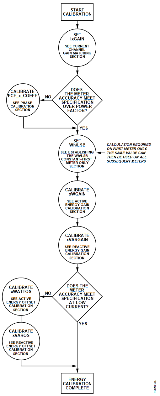
Figure 2. Active Energy Calibration Flow.
Current Channel Gain Matching
Because the ADE7816 has six current channels, it is convenient to match them all prior to calibrating. Matching the current channels results in easier computations because one bit in the rms and energy registers has the same weight on each channel. It is recommended that channel matching be performed as the first calibration step.
To match the six current channels, follow the procedure outlined in the Setting the IxGain Registers section.
Setting the IxGain Registers
To match all current channel, apply the same fixed input current to all six channels. This should be the nominal current as described in the Required Input Conditions section. The current rms readings can then be used to determine if there is any error between the six channels. For increased stability, synchronize the rms register readings to the ZX measurement. This reduces the effects of ripple in the readings caused by nonidealities of the internal filtering. See the ADE7816 data sheet for details on zero-crossing detection.
One channel, for example, Channel A, should be used as a reference. The IBGAIN (Address 0x4382), ICGAIN (Address 0x4383), IDGAIN (Address 0x4384), IEGAIN (Address 0x4385) and IFGAIN (Address 0x4386) registers can then be used to correct any mismatch from Channel A. The following equation describes how to adjust the IxRMS reading to match that in IARMS using the IxGAIN register:
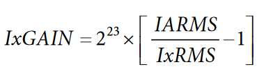
After all IxGAIN register have been set, all six channels should produce exactly the same IxRMS reading with a constant input.
Phase Calibration
Phase calibration is required when the current sensor being used introduces a phase shift. Current transformers can add significant phase shift that introduces large errors at low power factors. Phase calibration should be performed before gain or offset calibration because large phase corrections can alter the gain response of the ADE7816.
Phase calibration can be performed with a single inductive or capacitive load at a power factor of 0.5. If this load is not available, another power factor can be chosen; however, for best results, the power factor should be as close to 0.5 as possible. The following equation outlines how to determine the phase error in degrees:
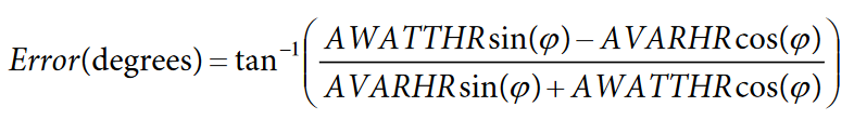
where Φ refers to the angle between the voltage and the current (in degrees).
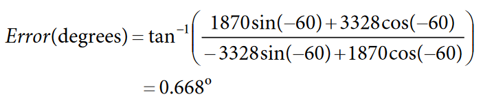
For example, if a LINECYC value of 500 half line cycles is set and the frequency of the input signal is 50 Hz, the accumulation time is 5 seconds (0.5 × (1/50) × 500). Assuming that a load of 220 V and 10 A at a power factor of 0.5 (inductive) produces an AWATTHR reading of 1870, and the AVARHR reading is −3328, the error in degrees can be determined as follows:
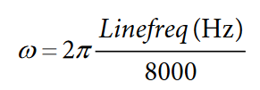
The ADE7816 uses all pass filters to accurately add time advances and delays to the current channels with respect to the voltage channels. A separate filter is included on each of the six current channels. To adjust the time delay or advance, the coefficient of these filters must be adjusted. Equation 1, Equation 2, and Equation 3 show how the coefficients correspond to the phase offset in radians.

where error(θ) is the phase error in degrees.
If PCF_x_COEFF ≥ 0, then:

If PCF_x_COEFF < 0, then:

Using the previous example, the required phase adjustment, θ, is 0.668°. The PCF_A_COEFF register setting can then be calculated as follows:
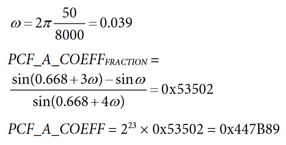
Analog Devices provides a spreadsheet to simplify this calculation. It is available at https://www.analog.com/ADE7816_tools_software_simulation.
Depending on the current sensors being used, different phase calibration values can be required on all six channels.
Establishing the Wh/LSB Constant—First Meter Only
When calibrating the first meter, the Wh/LSB constant must be determined. The Wh/LSB constant is used to set the weighting of each LSB in the active energy register. This constant allows the energy register readings to be converted into real-world values. Once established, the same Wh/LSB meter can be used for each subsequent meter.
To determine the Wh/LSB constant, use the following formula:

where:
Accumulation Time is the line-cycle accumulation time.
AWATTHR is the energy register reading after this time has elapsed.
For example, if a LINECYC value of 500 half line cycles is set and the frequency of the input signal is 50 Hz, the accumulation time is 5 seconds (0.5 × (1/50) × 500). Assuming a load of 220 V and 10 A produces an AWATTHR reading of 1909, the Wh/LSB constant can be calculated as:

To adjust the constant to meet a particular specification or to make the constant easier to store, the AWGAIN register can be used. The AWGAIN register can be used to modify the Wh/LSB constant by ±50%. The AWGAIN register affects the AWATTHR register as shown in the following formula:

To achieve a different meter constant, alter the AWATTHR reading based on the desired Wh/LSB.

For example, to alter the previously calculated Wh/LSB constant to 9 × 10⁻⁴, the desired AWATTHR reading is:
This adjustment can be made using the AWGAIN register as described in the Active Energy Gain Calibration section.
Active Energy Gain Calibration
The purpose of the active energy gain calibration is to compensate for small gain errors due to part-to-part variation in the internal reference voltage and external components such as the time error introduced by the crystal. Gain calibration is required on every meter and is performed with nominal voltage and current inputs at a power factor of 0.5 as previously described. For simplicity, it is recommended that all meters be calibrated to use the same Wh/LSB value, and this should be set up in the first meter as explained in the Establishing the Wh/LSB Constant—First Meter Only section.
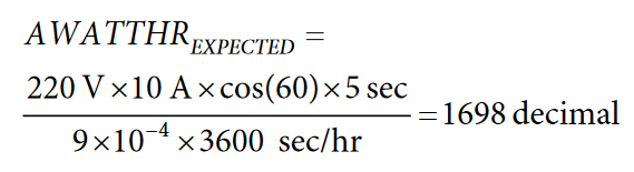
Use the following formula to determine the expected reading in the AWATTHR register:
The actual value can then be read from the AWATTHR register, and the AWGAIN register can be used to correct any error. The following formula shows how AWGAIN can be used to adjust the AWATTHR reading:
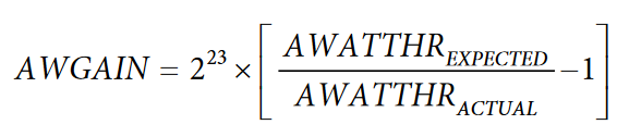
Using the previous example, at 220 V and 10 A, the expected AWATTHR reading is 1698 decimal. Assuming that the actual AWATTHR reading is 1600 decimal, AWGAIN is calculated as:

Note that the gain calibration for Channel B through Channel F is controlled by the BWGAIN, CWGAIN, EWGAIN, and FWGAIN registers. Assuming that the channels are correctly matched, as described in the Current Channel Gain Matching section, the previous procedure does not need to be repeated for the other channels. Write the value calculated for AWGAIN to BWGAIN, CWGAIN, EWGAIN, and FWGAIN for accurate results.
Reactive Energy Gain Calibration
Because the ADE7816 active and reactive energy measurements are closely matched, separate reactive energy gain calibration is not always required. In most cases, the values calculated for AWGAIN in the Active Energy Gain Calibration section can be written to the AVARGAIN register to retain the same VARhr/LSB constant.
If a different LSB weighting (that is, VARhr/LSB constant) or further calibration is required, the reactive energy can be calibrated separately. Reactive energy calibration should be performed with nominal inputs at a power factor of 0.5 as previously described. The reactive energy calibration is performed in a similar manner to the active energy calibration by first determining the expected xVARHR output.
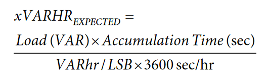
The compensation can then be determined by:

Note that the gain calibration for Channel B through Channel F is controlled by the BVARGAIN, CVARGAIN, EVARGAIN, and FVARGAIN registers. Assuming that the channels are correctly matched, as described in the Current Channel Gain Matching section, the previous procedure does not need to be repeated for the other channels. Write the value calculated for AVARGAIN to BVARGAIN, CVARGAIN, EVARGAIN, and FVARGAIN for accurate results.
Advanced Energy Offset Calibration (Optional)
Active Energy Offset Calibration
Active energy offset calibration is required only if accuracy at low loads is outside the required specification prior to offset calibration.
To correct for any voltage-to-current channel crosstalk that may degrade the accuracy of the measurements at low current levels, perform active energy offset calibration. A low level current signal must be applied to allow the offset magnitude to be measured and then removed.
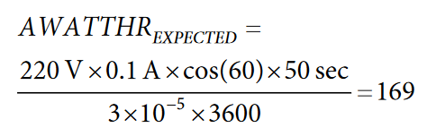
When performing offset calibration, it is often required to increase the accumulation time to minimize the resolution error. As the line-cycle accumulation mode accumulates energy over a fixed time, the result is accurate to ±1 LSB. If the number of bits accumulated in the xWATTHR register is small after this time, the ±1 LSB error can result in a large error in the output. For example, if only 10 bits are accumulated in the xWATTHR register, the resolution error is 10%. Increasing the number of accumulation bits to 1000 reduces the resolution error to 0.1%.
In the following example, a LINECYC value of 5000 half line cycles is set, and an input current of 100 mA is applied. With a voltage channel input of 220 V at a power factor of 0.5, the expected AWATTHR reading is determined as:
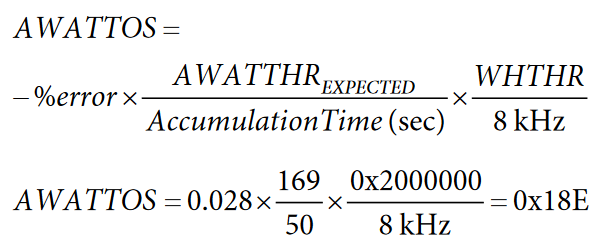
If the actual AWATTHR register reading is 165 at 100 mA, the percentage error due to offset is determined as:

The offset in the watt measurement is corrected according to:
Note that, depending on the board layout and the crosstalk on the meter design, Channel B through Channel F may need a separate offset calibration from Channel A. This can be achieved through the BWATTOS, CWATTOS, DWATTOS, EWATTOS,and FWATTOS registers. These registers correct the respective xWATTHR register reading in the same way that AWATTOS affects the AWATTHR register reading.
Reactive Energy Offset Calibration
Reactive energy offset calibration is only required if accuracy at low loads is outside the required specification prior to offset calibration.
To correct for any voltage-to-current channel crosstalk that may degrade the accuracy of the measurements at low current levels, reactive energy offset calibration is performed. A low level current signal must be applied to allow the offset magnitude to be measured and then removed.
When performing offset calibration, it is often required to increase the accumulation time to minimize the resolution error. Because the line-cycle accumulation mode accumulates energy over a fixed time, the result is accurate to ±1 LSB. If the number of bits accumulated in the xVARHR register is small after this time, the ±1 LSB error can result in a large error in the output. For example, if only 10 bits are accumulated in the xVARHR register, the resolution error is 10%. Increasing the number of accumulation bits to 1000 reduces the resolution error to 0.1%. The expected xVARHR reading is determined as:

The offset in the reactive energy measurement is corrected according to the following equation:

Note that, depending on the board layout and the crosstalk on the meter design, Channel B through Channel F may need aseparate offset calibration from Channel A. This can be achieved through the BVAROS, CVAROS, DVAROS, EVAROS, and FVAROS registers. These registers correct the respective xVARHR register reading in the same way that AVAROS affects the AVARHR register reading.
Current And Voltage RMS
Calibrating the voltage and current rms is only required if the instantaneous rms readings are required. RMS calibration does not affect the performance of the active or reactive energy.
Perform the rms calibration using the instantaneous rms register readings. The readings can be obtained from the IxRMS register and the VRMS register. For increased stability, synchronize the rms register readings to the ZX measurement. This reduces the effects of ripple in the readings caused by the nonidealities of the internal filtering. See the ADE7816 data sheet for details on zero-crossing detection.
The current and voltage rms readings require gain calibration to compensate for any part-to-part variations. Offset calibration may also be required on every meter to remove crosstalk that may degrade the accuracy of the readings at low signal inputs.
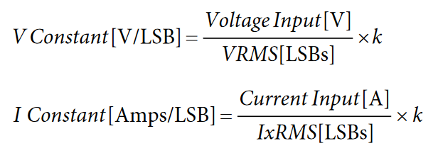
RMS Gain
Along with compensating for part-to-part gain variations, the rms gain constant converts the rms reading in LSBs into a current or voltage value in amps or volts. The voltage and current rms constants are determined under fixed load conditions by dividing the number of LSBs in the rms register by the amplitude of the input.
If the current channels have been correctly matched by following the procedure described in the Current Channel Gain Matching section, all current channels, A through F, should have the same I constant.
To maintain the full resolution when the conversion is taking place in the firmware, the voltage and current rms constants can be multiplied by a constant, k. The use of a multiplication factor, k, allows resolution to be maintained when converting and storing the rms readings as a hexadecimal number using fixed point multiplication. Converting the reading to the hexadecimal format is required prior to performing a hexadecimal-to-binary coded decimal conversion for display purposes.
An example of how the voltage rms register reading can be converted into a value in volts, while maintaining resolution of one digit below the decimal point, is provided in the following equation. In this example, 220 V is applied, producing a VRMS register reading of 3,400,000 decimal.

The volts/LSB constant is multiplied by a factor of 100 × 216 to maintain accuracy when using fixed point multiplication. The V constant is 0x1A8.
An additional example showing the generation of the current rms gain constant is provided in the following equation. In this example, the resulting LCD display measurement is accurate to two digits below the decimal point. A current input of 10 A is applied, resulting in an IRMS reading of 400,000 decimal.
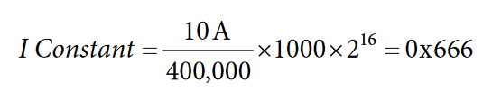
The amps/LSB constant is multiplied by a factor of 1000 × 216 to maintain the required accuracy during conversion. The resultingI constant is 0x666.
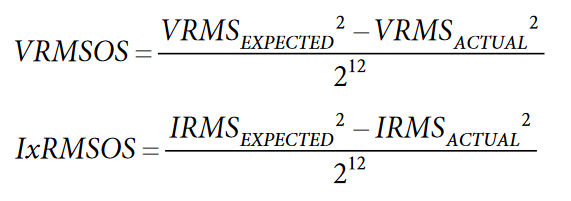
RMS Offset
To obtain accurate readings at low signal levels, the current and voltage rms offset may have to be calibrated. This calibration is performed using the internal VRMSOS and IxRMSOS registers that apply an offset prior to the square root function. The compensation factor is determined by applying the following equations:
As illustrated in Figure 3, the rms offset calibration is based on two points, where the expected reading is derived from the rms measurement with nominal inputs.

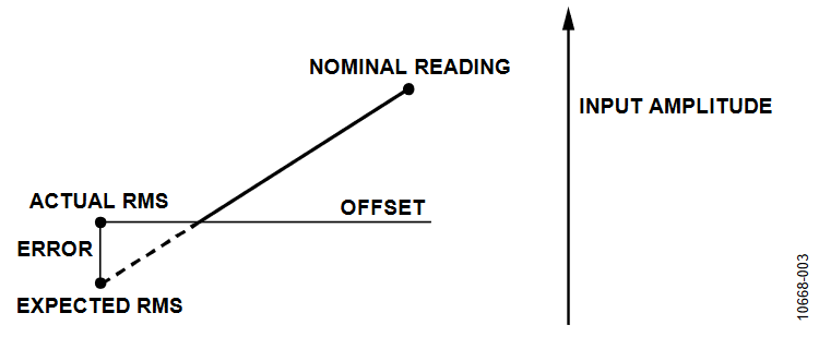
Figure 3. RMS Offset Compensation.
著者
