Abstract
Maxim Integrated® offers decades of Coupled Inductor (CL) experience and related IP with more than 60 issued US patents. Depending on customer specifications and priorities, the benefit of current ripple cancellation of coupled inductors can be traded for either smaller size or higher efficiency.
Dimensionless improvement for CL in multiphase buck converter compared to discrete inductor (DL) shows very significant benefit (Figures 1 and 2). This utilized benefit generally depends on duty cycle, number of coupled phases, and coupling coefficient Lm/Lk (mutual inductance divided by leakage). The benefit plot is shown in Figure 1 for a typical coupling Lm/Lk = 5. The red curve with a value of 1 corresponds to DL as a baseline, representing no improvement in current ripple cancellation.

Figure 1. CL benefit (FOM) as a function of duty cycle for a different number of coupled phases, Lm/Lk = 5.
Another observation is that coupling more phases generally increases the benefit, and that benefit can also increase a lot in certain areas of the duty cycle.
The normalized current ripple plot shows how the CL benefit translates to the current ripple reduction (Figure 2). The normalized current ripple, as a function of the duty cycle, shows the value of 1 for DL at D = 0.5. That DL ripple (red curve) is effectively divided by CL FOM from Figure 1. So, the current ripple decreases dramatically. In practice, this allows to either decrease the inductance value (for improved transient, and smaller size of magnetics and output capacitance) or decrease the switching frequency several times to dramatically reduce switching and other losses.

Figure 2. Normalized current ripple as a function of duty cycle for a different number of coupled phases, Lm/Lk = 5.
While coupling more phases is beneficial, another path for improvement is the coupling factor, especially valuable when many phases are coupled. The benefit curves for the eight coupled phases in Figure 3 suggest using the highest coupling ratio possible. In practice, it implies the implementation of the highest Lm as the application allows. Notice that the current ripple improvement due to increased coupling (basically increased Lm) does not have a drawback for the transient performance.

Figure 3. CL benefit (FOM) as a function of duty cycle for Nph = 8 and different values of coupling coefficient Lm/Lk.
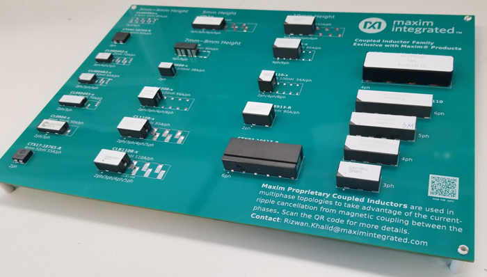
Several well-known and popular magnetics vendors have a free CL license from Maxim Integrated and can provide multiple sources for the needed parts to accompany its ICs. Maxim Integrated has already developed a CL portfolio for a wide range of possible customer applications, which is fully in production, and continues to work on the most recent and challenging customer requests. Some most popular magnetics designs are shown on a CL demo board in Figure 4.

Figure 4. CL demo board with the most popular designs.
It is very important that ICs and coupled inductors are developed simultaneously according to customer specifications, to work as a complete system in all application conditions. This includes efficiency performance, current-mode control that works with particular CL waveforms, feedback loops and current share, repetitive transient specifications, margin for possible current unbalance between phases, etc. A recently developed, more advanced magnetics design is shown in Figure 5.

Figure 5. Boosted coupled inductors.
Coupled inductors must work in all condition corners and specifications together with semiconductors and control. Therefore, CL specifications to vendors always come directly from Maxim Integrated after extensive development internally, and the actual performance is later carefully verified and approved by Maxim Integrated to ensure overall system performance for customers.
Maxim Integrated has more than 60 issued US patents for coupled inductors. It shares a lot of knowledge and know-how with its licensed coupled inductor manufacturers and customers.
Contact Maxim Integrated representatives and FAEs to learn how the company optimizes the solutions for specifications.


