Using the LT1719 Comparator for Low Dispersion Sine Wave to Square Wave Conversion
Using the LT1719 Comparator for Low Dispersion Sine Wave to Square Wave Conversion
Nov 1 1999
The LT1719 is an UltraFast™, 4.5ns comparator with separate analog and digital supplies. Both supplies can be as low as 2.7V, or the LT1719 can be used as a level translator in mixed 3V/5V systems. The propagation delay of comparators is typically specified for a 100mV step, with some fraction of that for overdrive. But in many signal-processing applications, such as in communications, the goal is to convert a sine wave, such as a carrier, to a square wave for use as a timing clock. The desired behavior is for the output timing to be dependent only on the input timing. No dispersion or phase shift should occur as a function of the input amplitude, as this would result in AM to FM conversion. The LT1719 is an excellent choice in these applications, particularly when the input signal is larger than 100mVP-P.
Test Circuit
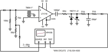
The circuit of Figure 1 was used to test an LT1719-based sine wave to square wave converter. The ±5V supplies on the input allow very large input swings; the 3V logic supply keeps the output swing small to minimize coupling back into the inputs. Characterization of the delay, which varies just a fraction of a nanosecond over a decade of input amplitude change, is not simple. A fast oscilloscope can have ±500ps of variation in any given channel. This can be calibrated by swapping input and output channels and averaging the readings if the two signals allow the same vertical scale factors. But for a measurement of delay changes over a decade or more of amplitude range, accuracy is degraded by delay dependence on the gain settings of the oscilloscope’s vertical path.

Figure 1. Sine to square wave converter schematic.
To characterize the delay, an HP4195 Spectrum/Network Analyzer was used to look at the phase of the output relative to the input (Test/Ref). Because the HP4195 is a spectrum/network analyzer, it can reject the harmonics of the output square wave, unlike some network-only analyzers. The phase of the fundamental component of the LT1719 output can be slightly affected by the exact nature of any overshoot or undershoot of the transitions, so a pair of antiparallel diodes is used to clip off these portions of the output waveform. The rest of the circuitry on the output is a filter whose exact behavior does not affect the measurement because the same amplitude and frequency signal will always be present there and only relative changes in phase will be examined.
The input signal is terminated in a resistive –12dB pad that creates the reference signal for the analyzer. The HP4195 maximum oscillator level is 15dBm or 3.56VP-P. The 1:2 transformer steps this up to 7.12VP-P differential at the DUT input. An amplifier could be used to boost the amplitude further, but distortion in the amplifier could result in phase errors because the LT1719 will respond to the zero-crossings, whereas the HP4195 will respond to the phase of the fundamental. The results without a transformer, grounding the unused comparator input, were unchanged but for the loss of 6dB.
Results
Figure 2 shows the time delay of the sine wave to square wave converter responding to an amplitude sweep at 10MHz. The delay is calculated as:

where θ is the phase in degrees measured by the network analyzer and tDELAY|0dBm is the absolute delay at 0dB input amplitude, which was measured with a fast oscilloscope using the calibration method described earlier. The LT1719 delay changes just 0.65ns over the 26dB amplitude range; 2.33 degrees at 10MHz. The delay is particularly flat, yielding excellent AM rejection, from –5dBm to 10dBm, a common range for RF signal levels.

Figure 2. Time delay vs sine wave input amplitude.
With small input signals, the hysteresis of the LT1719 (3.5mV typ.) and increased propagation delay make the LT1719 act like a comparator with a 12mV hysteresis span. In other words, a 12mVP-P sine wave at 10MHz will barely toggle the LT1719, but with 90° of phase lag or 25ns additional delay. Above 5VP-P at 10MHz, the LT1719 delay starts to decrease due to the internal capacitive feed-forward in the design of the input stage. Unlike some comparators, the LT1719 will not falsely anticipate a change in input polarity, but the feed-forward is enough to make a transition propagate through the LT1719 faster once the input polarity does change.
At frequencies higher than 10MHz, attention to detail in the physical construction of circuits becomes particularly important. With a poor layout, the output toggle action can capacitively or inductively couple back to the input signal, causing distortion. This must be avoided in order to measure the actual performance of the comparator. The LT1719 pinout has been optimized to shield the input signals from the digital signals with two intervening power supply pins.
Conclusion
The new LT1719 comparator can easily be used to create a low power, high performance, sine wave to square wave converter. The fast, 4.5ns delay barely changes with input amplitude fluctuations. The delay is particularly flat, for excellent AM rejection, from –5dBm to 10dBm.


