A Thermoelectric Cooler Temperature Controller for Fiber Optic Lasers
A Thermoelectric Cooler Temperature Controller for Fiber Optic Lasers
by
Jim Williams
Sep 1 2001
Introduction
Continued demands for increased bandwidth have resulted in deployment of fiber optic-based networks. The fiber optic lines, driven by solid state lasers, are capable of very high information density. Highly packed data schemes such as DWDM (dense wavelength division multiplexing) utilize multiple lasers driving a fiber to obtain large multichannel data streams. The narrow channel spacing relies on laser wavelength being controlled within 0.1nm (nanometer). Lasers are capable of this but temperature variation influences operation. Figure 1 plots typical laser wavelength vs temperature. The 0.1nm/°C slope means that although temperature facilitates tuning laser wavelength, it must not vary once the laser has been peaked. Typically, temperature control of 0.1°C is required to maintain laser operation well within 0.1nm.

Figure 1. Laser wavelength varies ≈0.1nm/°C. Typical application requires wavelength stability within 0.1nm, mandating temperature control.
Temperature Controller Requirements
The temperature controller must meet some unusual requirements.1 Most notably, because of ambient temperature variation and laser operation uncertainties, the controller must be capable of either sourcing or removing heat to maintain control. Peltier-based thermoelectric coolers (TEC) permit this but the controller must be truly bidirectional. Its heat flow control must not have dead zone or untoward dynamics in the “hot-to-cold” transition region. Additionally, the temperature controller must be a precision device capable of maintaining control well inside 0.1°C over time and temperature variations.
Laser based systems packaging is compact, necessitating small solution size with efficient operation to avoid excessive heat dissipation.
Finally, the controller must operate from a single, low voltage source and its (presumably switched mode) operation must not corrupt the supply with noise.
Temperature Controller Details
Figure 2, a schematic of the thermoelectric cooler (TEC) temperature controller, includes three basic sections. The DAC and the thermistor form a bridge, the output of which is amplified by A1. The LTC1923 controller is a pulse width modulator which provides appropriately modulated and phased drive to the power output stage. The laser is an electrically delicate and very expensive load. As such, the controller provides a variety of monitoring, limiting and overload protection capabilities. These include soft-start and overcurrent protection, TEC voltage and current sense and “out-of-bounds” temperature sensing. Aberrant operation results in circuit shutdown, preventing laser module damage. Two other features promote system level compatibility. A phase-locked loop based oscillator permits reliable clock synchronization of multiple LTC1923s in multilaser systems. Finally, the switched mode power delivery to the TEC is efficient but special considerations are required to ensure that switching related noise is not introduced (“reflected”) into the host power supply. The LTC1923 includes edge slew limiting which minimizes switching related harmonics by slowing down the power stages’ transition times. This greatly reduces high frequency harmonic content, preventing excessive switching related noise from corrupting the power supply or the laser.2 The switched mode power output stage, an “H-bridge” type, permits efficient bidirectional drive to the TEC, allowing either heating or cooling of the laser. The thermistor, TEC and laser, packaged at manufacture within the laser module, are tightly thermally coupled.

Figure 2. Detailed Schematic of TEC temperature controller includes A1 thermistor bridge amplifier, LTC1923 switched mode controller and power output H-Bridge. DAC establishes temperature setpoint; gain-adjust and compensation capacitor optimize loop-gain bandwidth. Various LTC1923 outputs permit monitoring TEC operating conditions.
The DAC permits adjusting temperature setpoint to any individual laser’s optimum operating point, normally specified for each laser. Controller gain and bandwidth adjustments optimize thermal loop response for best temperature stability.
Thermal Loop Considerations
The key to high performance temperature control is matching the controller’s gain bandwidth to the thermal feedback path. Theoretically, it is a simple matter to do this using conventional servo-feedback techniques. Practically, the long time constants and uncertain delays inherent in thermal systems present a challenge. The unfortunate relationship between servo systems and oscillators is very apparent in thermal control systems.
The thermal control loop can be very simply modeled as a network of resistors and capacitors. The resistors are equivalent to the thermal resistance and the capacitors to thermal capacity. In Figure 3 the TEC, TEC-sensor interface and sensor all have RC factors that contribute to a lumped delay in the system’s ability to respond. To prevent oscillation, gain bandwidth must be limited to account for this delay. Since high gain bandwidth is desirable for good control, the delays should be minimized. This is presumably addressed by the laser module’s purveyor at manufacture.
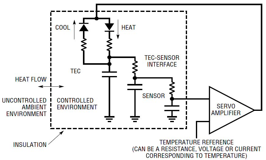
Figure 3. Simplified TEC control-loop model showing thermal terms: resistors and capacitors represent thermal resistance and capacity, respectively. Servo-amplifier gain bandwidth must accommodate lumped delay presented by thermal terms to avoid instability.
The model also includes insulation between the controlled environment and the uncontrolled ambient. The function of insulation is to keep the loss rate down so the temperature control device can keep up with the losses. For any given system, the higher the ratio between the TECsensor time constants and the insulation time constants, the better the performance of the control loop.3
Temperature Control Loop Optimization
Temperature control loop optimization begins with thermal characterization of the laser module. The previous section emphasized the importance of the ratio between the TEC-sensor and insulation time constants. Determination of this information places realistic bounds on achievable controller gain bandwidth. Figure 4 shows results when a typical laser module is subjected to a 40°C step change in ambient temperature. The laser module’s internal temperature, monitored by its thermistor, is plotted vs time with the TEC unpowered. An ambient-to-sensor lag measured in minutes shows a classic first order response.

Figure 4. Ambient-to-sensor lag characteristic for a typical laser module is set by package thermal resistance and capacity.
The TEC-sensor lumped delay is characterized by operating the laser module in Figure 2’s circuit with gain set at maximum and no compensation capacitor installed. Figure 5, measured at the LTC1923 error amplifier output, shows large-signal oscillation due to thermal lag dominating the loop. A great deal of valuable information is contained in this presentation.4 The frequency, primarily determined by TEC-sensor lag, implies limits on how much loop bandwidth is achievable. The high ratio of this frequency to the laser module’s thermal time constant (Figure 5) means a simple, dominant pole loop compensation will be effective. The saturation limited waveshape suggests excessive gain is driving the loop into full cooling and heating states. Finally, the asymmetric duty cycle reflects the TEC’s differing thermal efficiency in the cooling and heating modes.

Figure 5. Deliberate excess of loop gain bandwidth introduces large-signal oscillation. Oscillation frequency provides guidance for achievable closed-loop bandwidth. Duty cycle reveals asymmetric heating-cooling mode gains.
Controller gain bandwidth reduction from Figure 5’s extremes produced Figure 6’s display. The waveform results from a small step (≈0.1°C) change in temperature setpoint. Gain bandwidth is still excessively high, producing a damped, ringing response over 2 minutes in duration. The loop is just marginally stable. Figure 7’s test conditions are identical but gain bandwidth has been significantly reduced. Response is still not optimal but settling occurs in ≈4.5 seconds, about 25× faster than the previous case. Figure 8’s response, taken at further reduced gain bandwidth settings, is nearly critically damped and settles cleanly in about 2 seconds. A laser module optimized in this fashion will easily attenuate external temperature shifts by a factor of thousands without overshoots or excessive lags. Further, although there are substantial thermal differences between various laser modules, some generalized guidelines on gain bandwidth values are possible.5 A DC gain of 1000 is sufficient for required temperature control, with bandwidth below 1Hz providing adequate loop stability. Figure 2’s suggested gain and bandwidth values reflect these conclusions, although stability testing for any specific case is mandatory.
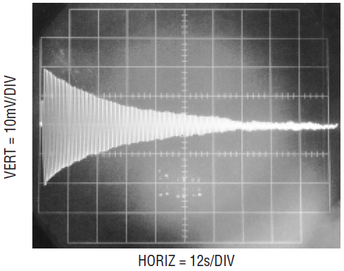
Figure 6. Loop response to small step in temperature setpoint. Gain bandwidth is excessively high, resulting in damped, ringing response over two minutes in duration.
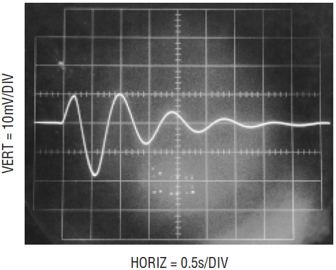
Figure 7. Same test conditions as Figure 7 but at reduced loop gain bandwidth: loop response is still not optimal but settling occurs in 4.5 seconds—over 25× faster than the previous case.
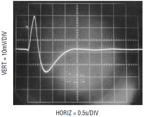
Figure 8. Gain bandwidth optimization results in nearly critically damped response with settling in 2 seconds.
Temperature Stability Verification
Once the loop has been optimized, temperature stability can be measured. Stability is verified by monitoring the thermistor bridge offset with a stable, calibrated differential amplifier.6 Figure 9 records ±1 millidegree baseline stability over 50 seconds in the cooling mode. A more stringent test measures longer term stability with significant variations in ambient temperature. Figure 10’s strip-chart recording measures cooling mode stability against an environment that steps 20°C above ambient every hour over 9 hours.7 The data shows 0.008°C resulting variation, indicating a thermal gain of 2500.8 The 0.0025°C baseline tilt over the 9 hour plot length derives from varying ambient temperature. Figure 11 uses identical test conditions, except that the controller operates in the heating mode. The TEC’s higher heating mode efficiency furnishes greater thermal gain, resulting in a 4× stability improvement to about 0.002°C variation. Baseline tilt, just detectable, shows a similar 4× improvement vs Figure 10.
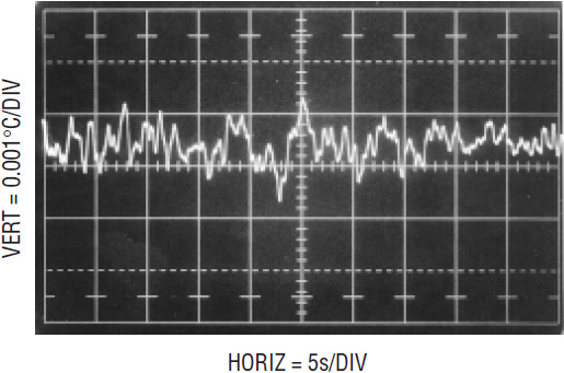
Figure 9. Short-term monitoring in room environment indicates 0.001°C cooling mode baseline stability.

Figure 10. Long-term cooling mode stability measured in environment that steps 20 degrees above ambient every hour. Data shows resulting 0.008°C peak-to-peak variation, indicating thermal gain of 2500. The 0.0025°C baseline tilt over plot length derives from varying ambient temperature.
This level of performance ensures the desired stable laser characteristics. Long-term (years) temperature stability is primarily determined by thermistor aging characteristics.9
Reflected Noise Performance
The switched mode power delivery to the TEC provides efficient operation but raises concerns about noise injected back into the host system via the power supply. In particular, the switching edge’s high frequency harmonic content can corrupt the power supply, causing system level problems. Such “reflected” noise can be troublesome to deal with. The LTC1923 avoids these issues by controlling the slew of its switching edges, minimizing high frequency harmonic content.10 This slowing down of switching transients typically reduces efficiency by only 1% to 2%, a small penalty for the greatly improved noise performance. Figure 12 shows noise and ripple at the suitably bypassed 5V supply with slew control in use. Low frequency ripple, 1mV in amplitude, is usually not a concern, as opposed to the high frequency transition related-components, which are only about 500µV in amplitude. Slew limiting effectiveness is measurable by disabling it. This is done in Figure 13, with a resulting 4.4× increase in high frequency content to about 2.2mV.

Figure 11. Identical test conditions to Figure 10, except in heating mode; The TEC’s higher heating mode efficiency results in higher thermal gain. 0.002°C peak-to-peak variation is 4× stability improvement. the baseline tilt, just detectable, shows similar 4× improvement vs Figure 10.

Figure 12. High frequency harmonic with slew limiting enabled: amplitude is 500µV.

Figure 13. Same conditions as previous figure, except slew limiting is disabled. Harmonic content amplitude rises to 2.2mV, a 4.4× degradation.
Conclusion
The LTC1923 provides the performance and features required for a complete laser temperature controller solution. The “hot–cold” control capability ensures the required temperature stability and the protection and monitoring capabilities protect the expensive laser.
Notes:
1. This article is excerpted from Linear Technology Application Note 89, “A Thermoelectric Cooler Temperature Controller for Fiber Optic Lasers.”
2. This technique derives from earlier efforts. See Linear Technology Application Note 70.
3. For the sake of text flow, this somewhat academic discussion must suffer brevity. However, additional thermodynamic gossip appears in LTC Application Note 89.
4. When a circuit “doesn’t work” because “it oscillates,” whether at millihertz or gigahertz, four burning questions should immediately dominate the pending investigation. What frequency does it oscillate at, what are the amplitude, duty cycle and waveshape? The solution invariably resides in the answers to these queries. Just stare thoughtfully at the waveform and the truth will bloom.
5. See Appendix A in Application Note 89, “Practical Considerations in Thermoelectric Cooler Based Control Loops,” for additional comment.
6. This measurement monitors thermistor stability. Laser temperature stability will be somewhat different due to slight thermal decoupling and variations in laser power dissipation. See Appendix A in Application Note 89.
7. That’s right, a strip-chart recording. Stubborn, locally based aberrants persist in their use of such archaic devices, forsaking more modern alternatives. Technical advantage could account for this choice, although deeply seated cultural bias may be a factor.
8. Thermal gain is temperature control aficionado jargon for the ratio of ambient-to-controlled temperature variation.
9. See Appendix A in Application Note 89 for additional information.
10. This technique derives from previous work. See Reference 2.
About the Authors
James M. Williams (April 14, 1948 – June 12, 2011) was an analog circuit designer and technical author who worked for the Massachusetts Institute of Technology (1968–1979), Philbrick, National Semiconductor (1979–1982) and
Related to this Article


