Abstract
The MAX2322 is a high-performance SiGe receiver front-end IC optimized for PCS (1900MHz) band CDMA (code division multiple access) applications. It includes an LNA, a mixer, and a selectable frequency LO buffer. This application note presents measured performance with the MAX2322 tuned for WCDMA (wideband CDMA) applications at 2.14GHz. The intermediate frequency (IF) used in this example is 190MHz. Analysis shows the front-end gain, noise figure and third order intercept are: 18.5dB, 5.8dB and -4.1dBm respectively.
Additional Information
Introduction
The MAX2322 is a high-performance SiGe receiver front-end IC optimized for PCS (1900MHz) band CDMA (code division multiple access) applications. It includes an LNA, a mixer, and a selectable frequency LO buffer. The LNA has three modes: high-gain high-linearity mode, high-gain low-linearity mode, and low-gain mode. These modes are controlled by LIN, GAIN, and SHDN pins. The mixer has a high IIP3 (input third-order intercept point), low noise, and a differential IF port. This application note presents measured performance with the MAX2322 tuned for WCDMA (wideband CDMA) applications at 2.14GHz. The intermediate frequency (IF) used in this example is 190MHz.

Figure 1. MAX2322 block diagram.
Application Circuit Performance
The LNA section achieves a gain of 13dB and a NF of 2dB, and the IIP3 is 8.8dBm. The input and output return losses are -11.1dB and -27.5dB, respectively. When switched into the low-gain mode, the gain decreases 10dB. Changing the bias resistor for the LNA allows the IIP3 and current consumption to be set, permitting design flexibility for your requirements.
The mixer section achieves a gain of 10.5dB and a NF of 9.3dB, and the IIP3 is 4dBm when the LO input level is -7dBm. This mixer is optimized for differential IF output, and a parallel 2kΩ resistor is needed for IF output matching. This board is tuned for 190MHz IF output and matched to 50Ωthrough a balun. On the evaluation board, a balun is used for easy interface to RF measurement equipment. The mixer also has an off-chip bias resistor. When the bias resistor is changed, IIP3 and current consumption values change.
The schematic is shown in Figure 8; the performance data is shown in Tables 1 and 2.
| LNA High-Gain Mode | ||||
| (unit) | 2110MHz | 2140MHz | 2170MHz | |
| NF | (dB) | 1.99 | 2.08 | 2.18 |
| Gain | (dB) | 13.13 | 12.78 | 12.51 |
| Input RL | (dB) | -11.43 | -11.85 | -11.56 |
| Output RL | (dB) | -31.35 | -27.53 | -23.46 |
| Input IP3 | (dBm) | 8.92 | 8.83 | 9.17 |
| ICC (IC total) | (mA) | 20.2 | ||
| LNA Low-Gain Mode | ||
| 2110MHz | 2140MHz | 2170MHz |
| 5.20 | 5.47 | 6.41 |
| -2.59 | -2.87 | -3.45 |
| -23.51 | -22.61 | -20.87 |
| -21.56 | -21.94 | -16.77 |
| 11.83 | 14.41 | 12.33 |
| 16.79 | ||
| (unit) | 2110MHz | 2140MHz | 2170MHz | |
| NF | (dB) | 9.82 | 9.36 | 10.15 |
| Gain | (dB) | 10.88 | 10.58 | 10.30 |
| Input IP3 | (dBm) | 4.00 | 4.00 | 3.91 |
The above tables do not include input and output transmission line losses.

Figure 2. S11 Smith Chart.

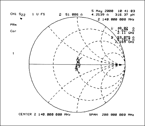
Figure 3. S22 Smith Chart.

Figure 4. S11.

Figure 5. S21.

Figure 6. S12.

Figure 7. S22.
Cascade Analysis
Assuming that the duplexer loss is 2dB and the interstate band pass filter (BPF) loss is 3dB, the cascaded performance is as follows:

| Gain | 18.5dB | -2dB | 13dB | -3dB | 10.5dB |
| NF | 5.8dB | 2dB | 2dB | 3dB | 9.3dB |
| IIP3 | -4.1dB | 8.8dBm | 4dBm |

Figure 8. MAX2322 application schematic.


