Abstract
Advances in wireless and IoT technologies are fueling the market growth of security camera systems. Outdoor security cameras must operate for a long time on small disposable batteries. This design solution shows how a high-performance power management system can power an outdoor security camera several months longer than an ordinary solution.
Introduction
The increasing usage of Internet of Things (IoT) and advances in wireless technology are propelling the wireless security market globally thanks to smartphones with wireless security options, battery and solar-powered wireless security systems, and wireless home-security cameras. On a more personal note, a security camera can help monitor your home from anywhere, helping you stay connected with family and pet, allowing you to check activities inside and outside. The latest outdoor security cameras are small while combining the convenient features of a smart home device with advanced camera technology. Security cameras will send alerts to your phone when they detect motion, record in high-definition, even at night, and are designed to withstand any type of weather. In this design solution we’ll review the challenges of powering an outdoor security camera system and provide a solution that extends its battery life operation to more than two years.

Figure 1. Wireless security camera in action.
Typical Security Camera System
Figure 2 shows a typical security camera block diagram. Two 1.5V, 3000mAh, AA lithium-ion batteries in series, supply a charge of up to 6000mAh to power the on-board imager, sensors, and radio through four ordinary DC-DC step-down voltage regulators.
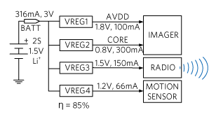
Figure 2. Security camera typical power management.
The system is normally in sleep mode. When motion is detected, the system wakes up. The camera starts recording and the radio transmits the data to a base station. The data is then moved to the cloud where it can be accessed remotely. The system is required to operate for a long time while being in sleep mode most of the time and be in recording and data transmission mode for an estimated 100 seconds per day.
In sleep mode, each buck converter in Figure 2 has a leakage current of 10µA. During operation at 85% efficiency, a 100-second pulse of a 316mA peak is drawn from the battery for motion sensing, recording, and data transmission. The simplified battery current draw over a one-day time span is shown in Figure 3.
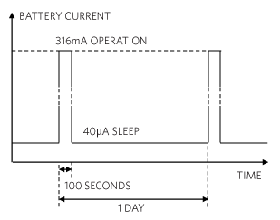
Figure 3. Security camera current profile.
Based on the above load profile, we can calculate the mAhr discharged in a day:
Daily Discharge = 316mA x 100s + 40µA x 24h = 9.737mAhr
Accordingly, a 6000mAh battery should last:

On the other hand, a high-performance regulator with 92% efficiency and a low quiescent current (0.33µA per regulator) will produce a pulse current of only 292mA (Figure 4).
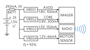
Figure 4. Security camera with high-performance power management.
Accordingly, its load profile is shown in Figure 5.
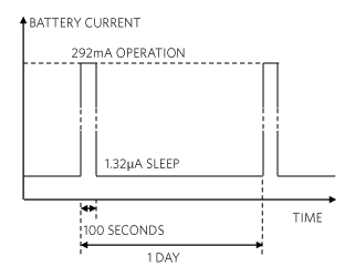
Figure 5. Security camera high-performance current profile.
Based on the above load profile we can calculate the mAhr discharged in a day:
Daily Discharge = 292mA x 100s + 1.32µA x 24h = 8.143mAhr
Accordingly, a 6000mAh battery should last:

The high-performance power management system outlasts an ordinary one by about 4 months!
The Challenges
Achieving high efficiency in a small size is challenging for any voltage regulator. Increasing the frequency of operation of the voltage regulator will reduce the size of passives but will result in increased losses, thereby reducing its efficiency. Having regulators that operate with low input voltage is critical, as the battery voltage falls continuously during operation. The proliferation of security camera applications creates a need for multiple customized versions of voltage regulators, especially with respect to input/output voltage and current specifications. Accordingly, the manufacturer may be forced to maintain a sizeable and costly inventory of different regulators and passives to support them.
A State-of-the-Art Solution
As an example, the MAX38640/MAX38641/MAX38642/MAX38643 family of nanoPower synchronous buck converters can meet this challenge. They offer high efficiency, along with a 1.8V to 5.5V input range and 175mA/350mA/750mA load current options. A 330nA ultra-low quiescent supply current and 5nA shutdown current make this a truly nanoPower device. Figure 6 shows the simplicity of this buck converter application circuit.
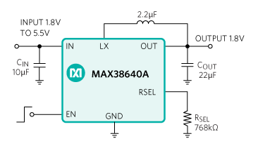
Figure 6. Simple application circuit of a high-performance buck converter.
The buck converter family eliminates the traditional resistor-divider that is used to set the output voltage value in favor of a single-output selection resistor (RSEL), as shown in Figure 4 (type A). Alternatively, several pre-selected output voltages are also available (Type B). The result is a small reduction in BOM (one or two less resistors), a simplified inventory (a single regulator for multiple applications), and lower quiescent current. Table 1 shows the buck converter family members in relation to the power tree in Figure 4.
| Device | Continuous Load Current | Application |
| MAX38640/MAX38641 | 175mA | VREG1 (100mA) VREG3 (150mA) VREG4 (66mA) |
| MAX38642 | 350mA | VREG2 (300mA) |
| MAX38643 | 700mA | Not Used |
Efficiency Advantage
The buck converter family of ICs features low-RDS(ON), on-board powertrain MOSFET transistors that yield excellent efficiency even when operating at frequencies high enough to warrant a small overall PCB size. Figure 7 shows an example of the MAX38640's efficiency.
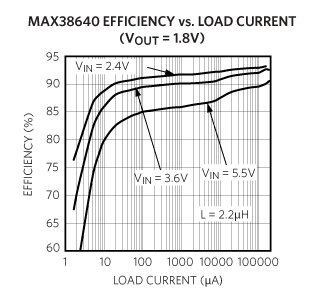
Figure 7. High-performance buck converter efficiency.
Conclusion
Security cameras help monitor your home from anywhere, help you stay connected with family and pets, and allow you to check activities inside and outside the home. Outdoor security cameras must be wireless and last a long time on small disposable batteries. In this design solution, we showed how the power management voltage regulator’s efficiency and quiescent current play a critical role in security camera battery life. For the system under consideration, the high-performance power management solution exceeded two years of operation, outlasting an ordinary solution by four months.
A similar version of this design solution originally appeared in All About Circuits on March 24, 2020.
Related to this Article
Products
Tiny 1.8V to 5.5V Input, 330nA IQ, 700mA nanoPower Buck Converter
Tiny 1.8V to 5.5V Input, 330nA IQ, 700mA nanoPower Buck Converter
Tiny 1.8V to 5.5V Input, 330nA IQ, 700mA nanoPower Buck Converter


