Short Ground Leads Make Better Scope Photos
I often ask customers to send me oscilloscope photos showing the ADC interface timing of their circuits. Occasionally, what I get back is a waveform with large amplitude ringing or even something that resembles a sine wave for what should be a relatively clean square wave. When asked how the scope probe was grounded, they will say that the standard ground lead was used. The standard ground lead on most scope probes is three to six inches long. The longer the ground lead, the more inductance it will have and the more likely that ringing will occur with fast rising edges.
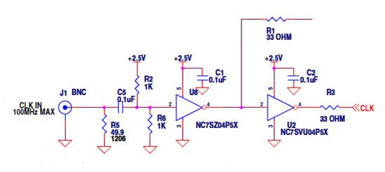
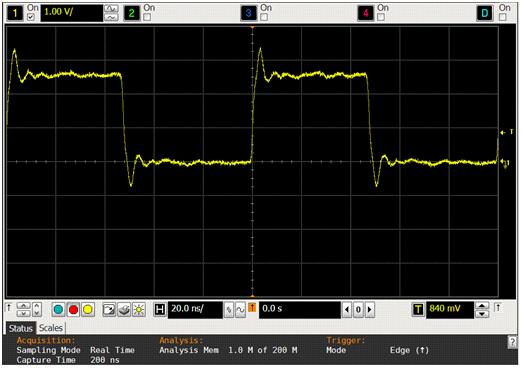
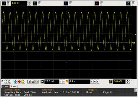
The following waveforms were taken using the DC1925A demo circuit. Figure 1 shows a portion of the schematic from the DC1925A. Figures 2 and 3 show 10MHz and 100MHz clock signals measured at the left side of R1 with the standard ground lead connected to the ground terminal of the board. The overshoot shown in these two figures is almost 1V above OVDD and 1V below ground. If this ringing were real, it could potentially damage devices connected to this node. The measurement setup for Figure 2 and Figure 3 is shown in Figure 4.
Figure 1. Partial DC1925A Schematic
Figure 2. 10MHz signal measured using standard scope ground lead
Figure 3. 100MHz signal measured using standard scope ground lead
Figure 4. Waveforms of Figure 2 and Figure 3 were taken using the standard ground lead for the scope probe
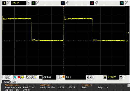
Removing the standard ground lead from the scope probe and winding a short piece of 24 gauge bus wire around the ground of the scope probe near the tip, will provide a much lower inductance path to ground the scope probe that can be connected to a nearby ground node on the PCB. Figure 5 and Figure 6 show the same 10MHz and 100MHz clock signals measured at the left side of R1 using the low inductance ground lead with the scope ground now connected to the bottom of R6. Not only is the amplitude of the ringing considerably smaller, the rise time is faster and the period of the ringing is much reduced. Figure 7 shows the measurement set up for Figure 5 and Figure 6.
Figure 5. 10MHz signal measured using low inductance ground lead
Figure 6. 100MHz signal measured using low inductance ground lead
Figure 7. Waveforms of Figure 5 and Figure 6 were taken using a short piece of bus wire as the scope ground lead and connecting it to a nearby ground node
Using the low inductance ground lead for the scope provides a much more accurate view of what is happening at the node being measured. Peak to peak amplitude, rise time and period of any overshoot are all much more accurately shown on the oscilloscope trace. This technique adds only a minute or two to the time required taking the measurement or if you remember to keep a few of these ground leads nearby, no extra time at all.
About the Authors
He began his career at LTC as a technician, learning from Bo...


