Ramp Three Supplies with a Supply Monitor and Hot Swap Controller
Ramp Three Supplies with a Supply Monitor and Hot Swap Controller
by
Mitchell Lee
May 1 2001
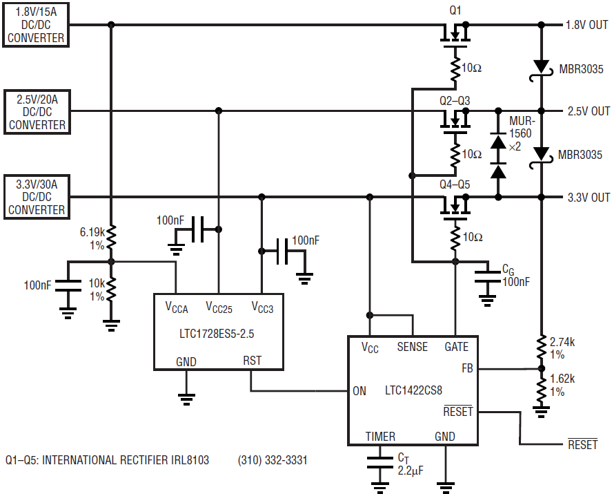
Many digital systems with multiple supply voltages require simultaneous ramping of supplies at power up. Since the power supply usually consists of separate regulators for each voltage, it is impossible to guarantee simultaneity of output. The circuit shown in Figure 1 ramps the outputs of three supplies and ensures tracking at power up and during recovery from a fault.

Figure 1. Ramping three supplies
Regulators invariably start up at different rates and different times based on current capability, filter capacitance and loop characteristics, so there are no guarantees as to how or when the outputs will rise to their respective voltages. In this case, an LTC1728-2.5 triple supply monitor keeps watch over each of three regulated supplies (1.8V, 2.5V and 3.3V). When all supplies rise to within acceptable limits (typically within 7.5% of the nominal output voltage), the LTC1728 waits 200ms and then enables an LTC1422 Hot Swap™ controller. The LTC1422 introduces an additional delay of approximately 1.4 seconds and then ramps the gates of three N-channel MOSFETs, one in series with the output of each supply. Figure 2 shows the relative timing of various waveforms during start-up.

Figure 2. Timing diagram
Arranged as source followers, the MOSFETs nominally track as the LTC1422 ramps a common gate node. The ramp rate is set by the GATE pin current and capacitor CG according to the equation

where IGATE is typically 17µA and CG is selected to limit the rate of rise and therefore the inrush current into any subsequent load capacitance.
The highest output, 3.3V, is the last to reach its final voltage. Its condition is monitored by the LTC1422’s FB pin, which releases RESET when the 3.3V MOSFET is fully on. RESET goes high after 1.4 second delay and, in turn, initiates load activity.
Faults
Output faults are handled by the short-circuit limiting of each individual DC/DC converter. Nevertheless, if a fault does occur, the effects are short lived. If one of the regulators goes into current limiting, its output will fall and the LTC1728’s RST output will go low. The LTC1422 then shuts off all of the outputs. This effectively removes the fault from the output of the affected regulator. The regulator output recovers and, after delays of 200ms and 1.4s, the LTC1422 tries to bring up the load again. If the fault persists, the regulator output will droop and the cycle repeats. Diodes are included across the outputs to guarantee worst-case differential levels under catastrophic fault conditions. Note that to compensate for MOSFET drops, the regulators are adjusted approximately 100mV higher than nominal.


