Power Management IC Digitally Monitors and Controls Eight Supplies
Power Management IC Digitally Monitors and Controls Eight Supplies
by
Andy Gardner
Sep 1 2009
Introduction
Today’s high reliability systems require complex digital power management solutions to sequence, supervise, monitor and margin a large number of voltage rails. Indeed, it is not unusual for a single application board to have dozens of rails, each with its own unique requirements. Typically the power management solutions for these systems require that several discrete devices controlled by an FPGA or a microcontroller are sprinkled around the board in order to sequence, supervise, monitor and margin the power supply array. In this scheme, significant time is required to develop the necessary firmware, and the tendency to underestimate the complexity and duration of that task is well known.
The LTC2978 octal PMBus power supply monitor and controller with EEPROM offers power supply system designers an integrated, modular solution that reduces debugging time and effort over microcontroller solutions. The LTC2978 can sequence on, sequence off, monitor, supervise, margin and trim up to eight power supplies. Multiple LTC2978s can be easily cascaded using the 1-wire share-clock bus and one or more bidirectional fault pins (Figure 1 shows a typical application).
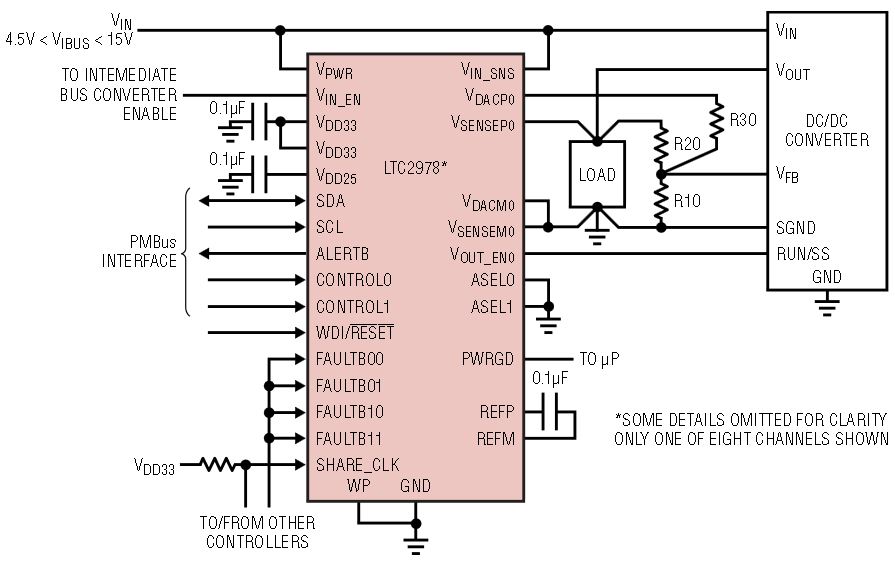
Figure 1. Octal power supply controller with PMBus communication. One channel is shown.
In addition, the LTC2978 uses a protected block of nonvolatile memory to record system voltage and fault information in the event of a critical system failure. Preserving critical system data in nonvolatile memory allows users to identify a failing voltage rail and isolate the cause of board failures during system development, test debug or failure analysis.
A free, downloadable graphical PC interface is available to facilitate interaction with the part in design and testing. The LTC2978 utilizes the industry standard PMBus command protocol in order to simplify firmware development. The LTC2978’s most important feature, though, is that its precision integrated reference and 15-bit ∆Σ ADC delivers ±0.25% absolute accuracy when measuring or adjusting power supply voltages.
Improve Manufacturing Yields with Precision Margin Testing
Margin testing of system voltages is an effective means of weeding out premature failures in high reliability systems. Typically, voltages are margined at least ±5% in order to guarantee that the system under test is robust enough to operate reliably in the field. Depending on system tolerances, however, this approach can lead to excessive test fallout. Many of these test rejects might have been avoided if the tolerances of the supply voltages in question were tighter.
With its precision reference, multiplexed 15-bit ∆Σ ADC, eight margin DACs and integrated servo algorithm, the LTC2978 offers a relatively easy-to-use, yet powerful, solution to this problem (see Figure 4 for the LTC2978 bock diagram). By simply writing an I2C command to either trim or margin to a specific voltage, the LTC2978 adjusts the DC/DC point-of-load converter within the prescribed software and hardware limits to deliver the commanded output voltage to ±0.25% absolute accuracy.
The margin DAC outputs are connected to the feedback nodes or trim inputs of the DC/DC POL converters via a resistor. The value of this resistor sets a limit on the range over which the output voltage can be margined, an important limitation for power supplies under software control. Another significant benefit of the 10-bit margin DACs is that they enable very fine resolution when margining voltages. This makes it possible to extract useful data from failure testing, as opposed to a trashcan full of failed, but not well understood, boards.
Flexible Power Sequencing and Fault Management
Many traditional power sequencing solutions rely on comparators and daisy-chained PCB connections. While relatively easy to implement for a handful of supplies, this approach quickly becomes complicated as the number of voltage rails grows, and is relatively inflexible in the face of specification changes. It’s also extremely difficult to implement turn-off sequencing with this type of approach.
The LTC2978 makes sequencing easy for any number of supplies. By using a time-based algorithm, users can dynamically sequence on and sequence off in any order (see Figure 2). Sequencing across multiple LTC2978s is also possible using the 1-wire share-clock bus and one or more of the bidirectional fault pins (see Figure 3). This approach greatly simplifies system design because channels can be sequenced in any order, regardless of which LTC2978 provides control. Additional LTC2978s can also be added later without having to worry about system constraints such as a limited supply of daughter card connector pins.
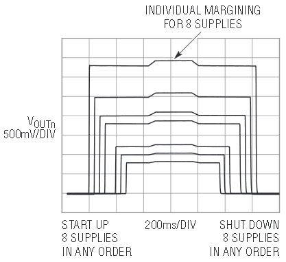
Figure 2. The LTC2978 offers flexible sequencing and precision margining.
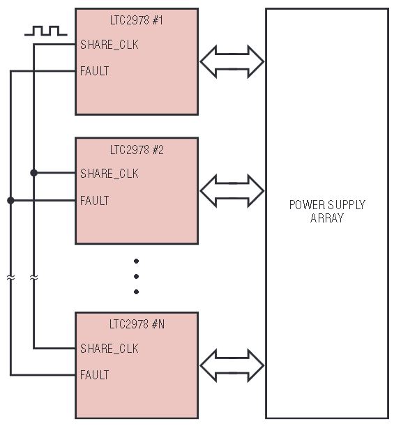
Figure 3. Multiple LTC2978s can be cascaded using only two connections.
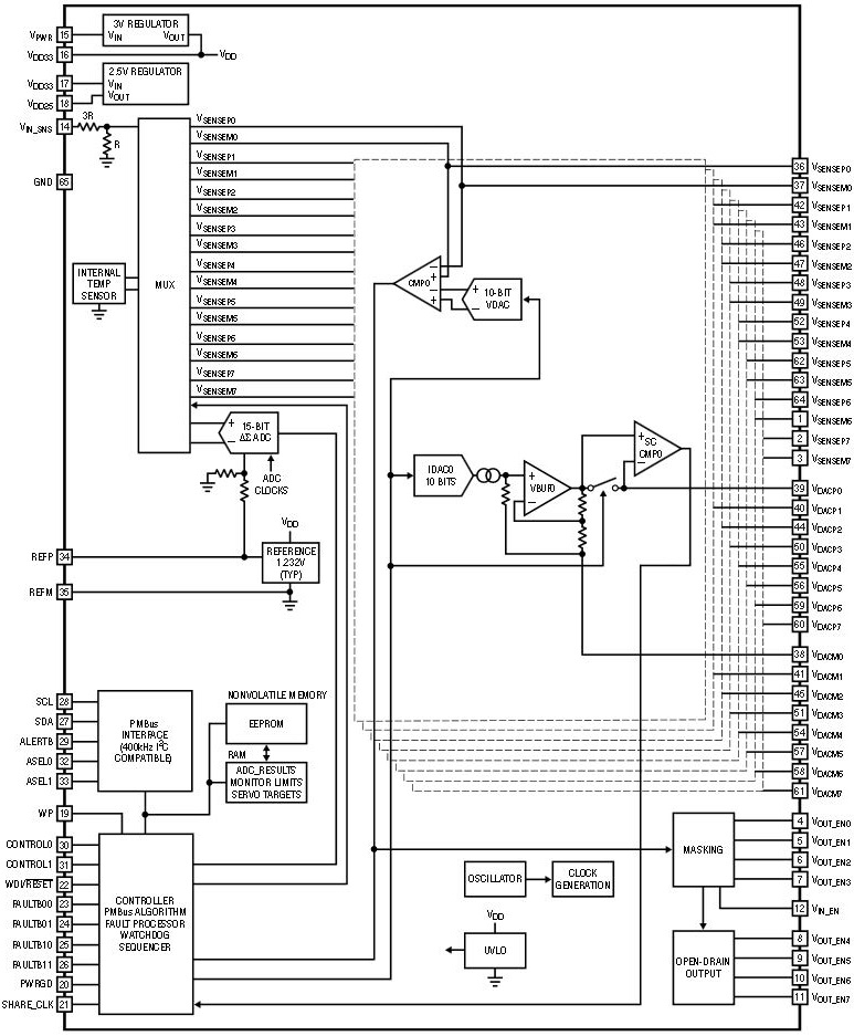
Figure 4. Block diagram of the LTC2978.
On sequencing can be triggered in response to a variety of conditions. For example, the LTC2978s can auto-sequence when the downstream DC/DC POL converters’ intermediate bus voltage exceeds a particular turn-on voltage. Alternatively, on sequencing can initiate in response to the rising- or falling-edge of the control pin input. Sequencing can also be initiated by a simple I2C command. The LTC2978 supports any combination of these conditions.
The bidirectional fault pins can be used for various fault response dependencies between channels. For instance, on sequencing can be aborted for one or more channels in the event of short-circuit. Once a rail has powered-up, the undervoltage supervisor function is enabled (the overvoltage function is always enabled). The overvoltage and undervoltage thresholds and response times of the voltage supervisors are all programmable. In addition, input voltage and temperature are also monitored. If any of these quantities exceed their over- or under-value limits, the customer can select from a rich variety of fault responses. Examples include immediate latchoff, deglitched latchoff, and latchoff with retry.
An integrated watchdog timer is available for supervising external microcontrollers. Two timeout intervals are available: the first watchdog interval and subsequent intervals. This makes it possible to specify a longer timeout interval for the micro just after the assertion of the power good signal. In the event of a watchdog fault, the LTC2978 can be configured to reset the micro for a predetermined amount of time before reasserting the power good output.
Multifaceted Telemetry
The LTC2978 serves up a variety of telemetry data in its registers. The multiplexed, 15-bit ∆Σ ADC monitors input and output voltages and on-chip temperature, storing minimum and maximum values for all voltages and temperature readings. In addition, the ADC inputs for odd-numbered output channels can be reconfigured to measure sense resistor voltages. In this mode, the ∆Σ ADC can resolve voltages down to 15.3μV, which is invaluable when attempting to measure current with inductor DCR circuits.
Although the LTC2978 can be directly powered from a 3.0V to 3.6V supply, the ADC is capable of accepting input voltages of up to 6V—no need to worry about body diodes or exotic standby supply voltages. The LTC2978 can also run off of a 4.5V to 15V input supply using its internal regulator. A separate high voltage (15V max) sense input is provided for measuring the input supply voltage for the DC/DC POL converters controlled by the LTC2978.
Black Box Data Recorder
In the event a channel is disabled in response to a fault, the LTC2978’s data log can be dumped into protected EEPROM. This 255-byte block of data is held in NVM until it is cleared with an I2C command. The data block contains output and input voltages and temperature data for the 500ms preceding the fault as well as the corresponding minimum and maximum values. Status register values and total up time since the last system reset are also stored in the log.
Figure 5 shows the data log contents viewed in the PC-based LTC2978 interface. In this way, the LTC2978 provides a complete snapshot of the state of the power system immediately preceding the critical fault, thus making it possible to isolate the source of the fault well after the fact. This is an invaluable feature for debugging both prerelease characterization or in-field failures in high reliability systems.
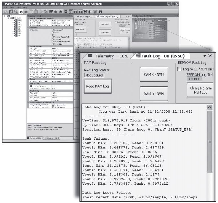
Figure 5. The LTC2978 comes with free software that allows easy data monitoring and cofiguration. The data log shows monitor readings just before a failure for debugging analysis.
Graphical User Interface and PMBus
Analog Devices' easy-to-use PC-based graphical user interface (GUI) allows users to configure the LTC2978 via a USB interface and a dongle card. The GUI, which is free and downloadable, takes much of the coding out of the development process and improves time-to-market by allowing the designer to configure all device parameters within an intuitive framework. Once the device configuration has been selected, the designer can save the parameters to a file and upload it to the LTC factory. LTC can use the file to pre-program parts, thus allowing the customer to bring up their boards with minimum hassle.
The LTC2978 utilizes the industry standard PMBus interface protocol which is a superset of the I2C compatible SMBus standard. PMBus is an open and widely adopted standard that clearly defines the protocols for digital power management of individual DC/DC POL converters. The LTC2978 supports a large number of the PMBus commands. It also features a number of DC/DC converter manufacturer-specific commands to keep complexity low and versatility high.
Conclusion
With its unprecedented parametric accuracy, rich feature set, and modular architecture, the LTC2978 is an ideal solution for managing large arrays of DC/DC POL converters.
The industry standard PMBus interface, free PC-based graphical setup software, and integrated EEPROM make it easy to customize the LTC2978 for any application. Designers can use the PC-based graphical interface to configure a device and upload the configuration to the LTC factory. From this, Analog Devices can provide ready-to-use, pre-programmed devices, customized for the particular application.
Other features include an integrated precision reference, a multiplexed 15-bit ∆Σ ADC, eight 10-bit voltage-buffered IDACs, eight overvoltage and undervoltage 10-bit voltage supervisors with programmable thresholds and response times, and an integrated EEPROM for storing configuration parameters and fault-log information. The LTC2978 is offered in a 64-lead 9mm × 9mm QFN package.


