Optimize the FM Path of the MAX2538 Using a Passive LC Balun
Abstract
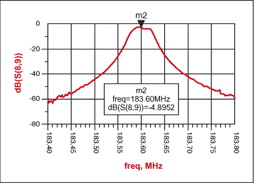
This application note describes the design of the interface to a single ended FM IF filter at 183.6MHz. A passive LC network, using a "balun," provides the needed balanced to unbalanced interface required. The design uses 4 inductors and 3 capacitors. Insertion loss is 4.9dB through the matching network and FM filter.
The MAX2538 cellular front-end IC has a dedicated mixer for the AMPS cellular signal path. The cellular-band LNA (low noise amplifier) (869 to 894MHz) is common to both AMPS and cellular CDMA (code division multiple access). The mixer design is double-balanced for optimum noise and LO (local oscillator) suppression. The IC pinout for this mixer provides a differential IF output, but single-ended RF input.
Analog Devices' V3.5 cellular phone reference design employs an FM IF filter with single-ended inputs and outputs, so it is necessary to transform the differential mixer output to single ended operation. The difficulty in designing a discrete L-C balun (balanced to unbalanced transformer) is mainly attributed to the high impedance transformation ("Z") ratio from the mixer output (~3.3 kilΩ) to the IF filter input (180 Ω). This represents a 18:1 Z-ratio which is very difficult to realize in a single section transformer. We have found that a 4:1 transformation ratio is a practical limit for the low amounts of insertion loss. To keep parts count to a minimum, a 1.5dB insertion loss compromise was achieved with a single-order LC design.
Below is an example of how to design a balanced to unbalanced LC transformer and also how to match the FM filter.
The mixer internal source impedance looks like 12 kilΩ || (in parallel with) 0.75pF. A 3.3 kilΩ external load resistor is selected for best overall tradeoff of mixer IIP3 (input third order intercept), gain and NF (noise figure). To best use the MAX2538 capabilities, these should be targeted for approximately +7dBm, 13dB, and 8.5 dB. A resistive load also maintains the wideband termination to absorb out of band reflections, which severely degrade intermodulation performance.
Step 1:
From simulation of the MAX2538 FM mixer, the output impedance model was extracted. To simplify and properly simulate the FM mixer's balanced to unbalanced L-C transformer and FM filter matching network, it is convenient to combine the IF load resistor with the Mixer's output model and convert the differential parallel circuit to a differential series equivalent circuit.

Figure 1. Model the mixer output impedance to simplify the design.
Step 2:
The FM filter input and output model must be known at the frequency of interest. The filter used is from Toyocom part# TF3-J3DC5 (183.6MHz)

Figure 2. FM filter input and output impedance.
Step 3:
RF simulation software is now used to simulate the Toyocom FM filter using the filter's 2 port S-parameters and also use ideal component values to establish a point of reference(see Figure 3). Figure 4 shows the ideal frequency response. This point of reference gives the ideal performance. Once real inductors models are used, the performance will degrade due to the lower quality factor (Q) of the real inductors. Wire-wound inductors with High-Q values should be used in the practical implementation to reduce the insertion loss. The capacitors used in this application should be ceramic monolithic chip capacitors, since their Q is greater than 200 at 183.6MHz and will introduce minimal insertion loss.

Figure 3. Single ended matching network with ideal components serves as starting point for the design.

Figure 4. Ideal FM filter performance.
Step 4:
Once we know the filter's input and output impedance and frequency response, the L-C balanced to unbalanced (balun) transformer can be designed. The transformer will resonate at 183.6MHz. Using the formula below we can calculate the resonant frequency of the circuit.

If we chose L = 238.5nH and C = 3.15pF (choose 2.4pF + 0.75pF from the mixer model = 3.15pF), Fo = 183.6MHz.
The filter's input impedance is 55.49 - j64.33Ω, therefore; the circuit below will match the mixer's output impedance to 55.49Ω first. Since, the balanced to unbalanced L-C transformer is not ideal and the inductors used have Q's of 35, then the circuit will have insertion loss and will not resonate at 183.6MHz using the original 238.5nH inductors. Therefore, the design must be re-tuned to resonate at 183.6MHz using 220nH see Figure 5. The circuit in Figure 5 has an insertion loss of -1.44dB see Figure 6.

Figure 5. Design is tuned to resonate at 183.6 MHz with 220 nH inductors.

Figure 6.
Step 5:
Finally, the balanced to unbalanced L-C transformer is matched to the Toyocom FM filter.

Figure 7. Final design uses 3 capacitors.

Figure 8. Frequency response of completed design.
Conclusion
The balanced to unbalanced L-C transformer is designed with a minimal number of discrete components -- 2 inductors and 1 capacitor -- and the insertion loss is kept to a minimum. The loss through the balanced to unbalanced L-C transformer is -1.44dB and the insertion loss through the FM filter at 183.6MH is -3.16dB. Figure 7 shows the circuit used and the performance is shown in Figure 8.


