Abstract
This application note discusses primary mechanisms that affect the design and performance of cellular-band CDMA handsets. Specific discussion topics include reciprocal mixing and cross-modulation. Bench results demonstrate system performance from Analog's V3.5 CDMA reference design.
Introduction
The CDMA cellular radio system was designed to operate within the same radio-frequency spectrum as the older Advanced Mobile Phone System (AMPS), which preceded CDMA in the US cellular band. The AMPS RF scheme employs many closely spaced and relatively narrow-band FM channels. In contrast, the CDMA RF scheme employs fewer but wider band RF channels. As a result, CDMA channel planning must include the existing AMPS channels, which can degrade CDMA links by acting as interferers.
In this application note we discuss two primary mechanisms that affect the design and performance of cellular-band CDMA handsets:
- Reciprocal mixing, in which the LO phase noise jams the desired incoming RF
- Cross-modulation, in which leakage from the handset transmitter overdrives the LNA
We also demonstrate good CDMA system performance by providing measurements on an actual system.
Background of Cellular-Band Frequency Plan
AMPS service resides in band segments of the 850MHz US cellular band:
- 824MHz to 849MHz uplink (reverse-channel band for transmitter on the handset)
- 869MHz to 894MHz downlink (forward-channel band for receiver on the handset)
AMPS channels are spaced 30kHz apart, and at peak deviation each occupies roughly 24kHz.
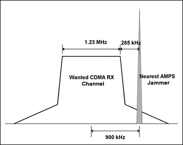
CDMA service occupies the same US cellular band as AMPS, and CDMA channels are aligned on the 30kHz AMPS raster (i.e., adjacent channels span a multiple of 30kHz). Each CDMA channel, however, occupies 1.23MHz of bandwidth. To manage that distribution, mobile-phone carriers are allocated 12.5MHz band segments. The nearest AMPS channel is set 285kHz away from the edge of the nearest CDMA channel, at the band-segment boundary (i.e., nine of the 30kHz AMPS channels plus 15kHz to the channel center). See Figure 1.

Figure 1. Relationship between a CDMA channel and the nearest AMPS carrier, which acts as an interferer to the CDMA channel.
When the nearest AMPS channel is much stronger than the CDMA signal level, the AMPS channel acts as single-tone interferer to the CDMA channel. The interferer frequency offset is shown by Equation 1:

Thus, 285kHz + 615kHz = 900kHz, which is the offset from the nearest interfering AMPS channel to the center of the desired CDMA channel. The power level of this interferer, relative to the sensitivity level of the desired CDMA channel (-101dBm), is established in the 3GPP2 Air-Interface Standard as a test tone at -30dBm, worst case.
Specification of Single-Tone Desensitization for CDMA Handsets
Single-tone desensitization measures the ability of a cell phone to receive a CDMA signal at its assigned channel frequency, in the presence of a nearby narrow-band jammer spaced at a given frequency offset from the center frequency of the assigned channel. Receiver desensitization is measured by the frame error rate (FER)1.
It is a primary advantage of CDMA systems that 25 or more handsets can operate directly on top of each other, that is, on the same channel center. For code-division multiplexing (channel differentiation), the uplink and downlink carriers for each handset are assigned different and orthogonal spreading codes.
To accomplish this latter task, the CDMA base station must accurately control the power from each handset transmitter so that all user signals are received at nearly the same incident power level. To comply with this requirement, the handset receiver must operate over a very wide gain-control range. When a CDMA handset receiver is farthest from the base station, the typical signals in its forward path are only -110dBm.
A problem arises because the adjacent AMPS system does not manage the cell phone's uplink power in the same way. It is possible (especially at cell-site boundaries) for a nearby AMPS base station to send a strong interferer while the CDMA handset is receiving at or near its sensitivity limit.
Fortunately, properties of the downlink spreading code make the CDMA handset receiver relatively immune to near-channel interferers. The narrowband AMPS interferer is 'spread' in the handset correlator, so that its impact is reduced by the processing gain (about 25dB). Because the interference is considerable, a test is specified to ensure that the CDMA receiver can adequately manage near-channel intrusions. The 3GPP2 CDMA2000 standard specifies the following test conditions for a single-tone desensitization test:
For CDMA systems in the US, the cellular-band test requirement specifies a minimum effective isotropic radiated power of +23dBm. The PCS-band test requirement specifies minimum effective isotropic radiated power of +15dBm (Tests 1 and 2) and +20dBm (Tests 3 and 4). Jammer levels are specified at
When testing a CDMA front-end IC or a zero-IF receiver for single-tone desensitization, it is important to note the interference components created by the single-tone jammer, and to recreate those effects in the test setup. Two main contributors affect single-tone desensitization: reciprocal mixing and cross modulation.
Reciprocal Mixing
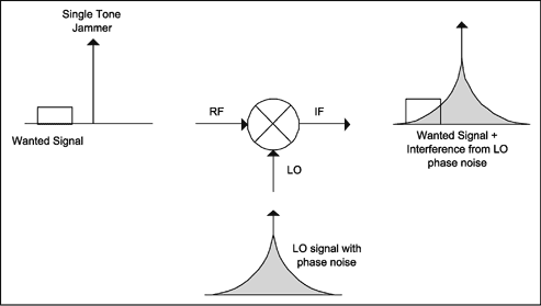
Reciprocal mixing occurs when a single-tone jammer mixes with the receiver's local oscillator signal (Rx LO). Rx LO has finite phase noise, which mixes with the single-tone jammer and creates an interference component at the intermediate frequency (IF) or baseband in the case of a zero-IF system (Figure 2).

Figure 2. Reciprocal mixing in the presence of a jammer.
The receiver single-tone desensitization specification is a key performance parameter that sets the LO phase-noise requirement. For accurate single-tone desensitization measurements, note that the single-tone jammer's own phase noise also contributes to the overall interference level. For lab tests you should, therefore, choose an RF-signal source with low phase noise. This will ensure that the main contributor to single-tone desensitization comes from phase noise in the Rx LO, rather than from the RF signal generator.
As an example, consider Analog's superheterodyne CDMA reference design (Version 3.5), which uses the MAX2538 front-end IC and the MAX2308 IF demodulator IC. The receiver has a cascaded noise figure (referred to the LNA input) of less than 3dB in the cellular band. If we assume a duplexer/diplexer loss of about 3dB in a mobile handset, we have in Equation 2:

If phase noise in the RF signal generator is 10dB below the receiver noise floor, then:

where -30dBm is the specified single-tone level per Tests 1 and 2 (Table 1). Equation 4, therefore, expresses new receiver noise floor as:

The impact, consequently, of -148dBc/Hz phase noise in the RF signal generator is a relatively small rise (only 0.4dB degradation) in the receiver sensitivity.
The CDMA handset standard calls for a minimum phase noise of -144dBc/Hz at the 900kHz offset frequency. Assuming a flat response for far phase noise (-144dBc/Hz across the band of interest), then the preceding calculations give a receiver noise floor of -167dBm/Hz. That level is 1dB worse than the -168dBm/Hz noise floor with no interferer. Thus, the CDMA standard allows receiver sensitivity and desensitization to degrade by 1dB, due to the RF interference generator.
| Parameter | Units | Tests 1 and 3 | Tests 2 and 4 | |
| Tone offset from carrier | SR1 | kHz | +900 (BC 0, 2, 3, 5, 7 and 9) +1250 (BC 1, 4 and 8) |
-900 (BC 0, 2, 3, 5, 7 and 9) -1250 (BC 1, 4 and 8) |
| SR3 | kHz | +2500 | -2500 | |
| Tone power | dBm | -30 (Tests 1 and 2) -40 (Tests 3 and 4) |
||
 |
dBm/1.23MHz | -101 | ||
 |
dB | -7 | ||
 |
dB | -15.6 (SR1) -20.6 (SR3) |
||
Cross-Modulation Interference
Cross modulation occurs when a strong transmitter-leakage signal is present at the receiver's LNA input. This modulated interferer is cross-modulated with the 900kHz AMPS tone by third-order nonlinearities in the LNA. The resulting cross-modulation is an increase in noise power at the desired RF channel in the receiver. Even though the receiver's IP3 is dominated by the mixer's IP3, most of the cross-modulation occurs in the LNA. This happens because TX leakage at the mixer input is very small due to the bandpass filter between LNA and mixer.4 To include this effect in a receiver test setup, you must inject a CDMA reverse-channel modulated signal into the receiver. For cellular band, the Tx power injected into the LNA input is expressed as Equation 5:

This equation assumes a Tx rejection of 52dB at the Rx port of the duplexer, and 2dB of loss from antenna to the Tx port of the duplexer.
Test Example Using the CNR Method
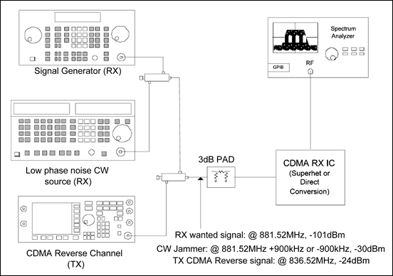
Figure 3 shows the complete single-tone desensitization setup for testing a CDMA receiver in the cellular band. The same setup is usable for PCS-band testing, but the jammer offset and levels for the jammer and Tx signals must be set according to the test specification shown in Table 1 above. In this test setup, we use the CNR (carrier-to-noise ratio) method to measure single-tone desensitization.

Figure 3. Cellular single-tone desensitization setup.
Sensitivity is defined as the minimum received power at which the frame error rate (FER) is < 0.5% for 95% of the time. In the CNR measurement, we note that for Radio Configuration1 in the 3GPP2 standard, the Traffic Ec/Ior is -15.6dB, and that Traffic Eb/Nt = 4.5dB for a data rate of 9600bps. The processing gain is 10log (1.2288Mcps/9600bps) = 21.072dB. Consequently, we have Equation 6:

Therefore, the required CNR for demodulating CDMA signals is -1dB, measured in the 1.23MHz channel bandwidth. We use an RBW setting of 3kHz for our test setup, and compare the beat-note test tone power (at 250kHz) to the total integrated channel-noise power over the 615kHz I-Channel bandwidth. Because the desired signal power received is -101dBm and our total allowed noise power is
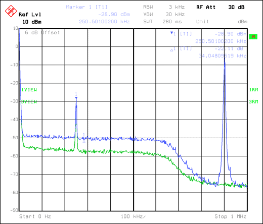
To demonstrate this method, consider a measurement taken on Analog's N-CDMA V4.1 reference design, using a zero-IF monolithic receiver IC (MAX2585) with on-chip VCO (Figure 4). The green trace shows the desired signal in the absence of a jammer or Tx signal. (For the desired signal, we use a single tone injected at 250kHz, offset from the channel frequency at -101dBm, instead of a CDMA forward-channel modulated signal.) The blue trace shows the rise in noise when the jammer and CDMA Tx signal are turned on together. The following procedure outlines the test setup:

Figure 4. Noise rise due to single-tone jammer and CDMA TX signal.
- Adjust the system gain to receive an input of -101dBm referred to the input of the 3dB pad. This action simulates duplexer loss. For the MAX2585 receiver IC, set the gain for a nominal output-signal level of 8.5mVRMS (-28.5dBm into 50Ω).
- Turn on the CDMA Tx signal (45MHz below the Rx channel frequency, referred to the input of 3dB pad) at -24dBm.
- Turn on the CW jammer tone at -30dBm, referred to the input of the 3dB pad. Observe the noise floor rise.
- Adjust the CW jammer level for a noise-floor rise so that the total integrated noise power from baseband to 615kHz is 1dB above the desired signal level. In this example, we integrate from 25kHz to 615kHz to avoid DC leakage from the analyzer.
- Record the jammer level at -1dB CNR, and calculate the single-tone desensitization margin.
In this example, the total noise power integrated from 25kHz to 615kHz is -27.5dBm. The received tone at the output is -28.5dBm, which satisfies the -1dB CNR requirement. The single-tone jammer level is -27dBm at the -1dB CNR point, which indicates that the MAX2585 IC meets the requirements of single-tone desensitization with a 3dB margin at the tested frequency.
Summary
This article discussed single-tone desensitization per the 3GPP2 standard and important contributors to single-tone desensitization. A practical method for measuring single-tone desensitization in a CDMA receiver was presented. For further information on superheterodyne and direct-conversion receiver ICs from Analog, please visit the Analog website: Wireless, RF, and Cable ICs.
A similar article appeared in the May, 2005 edition of RF Design.
Related to this Article
Products
Advanced Multimode Complete RF-to-Baseband Receiver
CDMA IF VGAs and I/Q Demodulators with VCO and Synthesizer
Quadruple-Mode PCS/Cellular/GPS LNA/Mixers


