LTspice® How-to: Using the .STEP Directive to Perform Repeated Analysis
Updated June 2026
Abstract
The .STEP directive in LTspice enables an easy way to sweep circuit parameter values and observe the results overlaid in a single waveform window. This allows for a quick understanding of circuit behavior and design trade-offs.
Introduction
LTspice can be used to refine circuit design decisions through trial and error: modify a circuit element and observe the changed outcome. This examination is often done manually, but the .STEP directive in LTspice provides the capability to run multiple variations of a circuit and view the results in a single waveform window.
Using a Parameter to Define a Component Value
To implement the .STEP directive, start by defining the parameter to be stepped. Figure 1 shows an example—a pulse is applied to an RC circuit, and the response at OUT is observed on the waveform. This example circuit can be downloaded at Step-Example.asc.
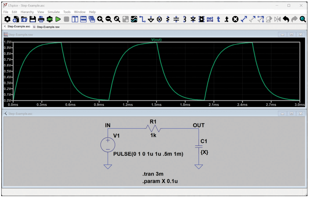
Run the simulation by pressing Alt + R (or Simulate -> Run/Pause from the menu). Click on the OUT node to plot the results in the Waveform Viewer.
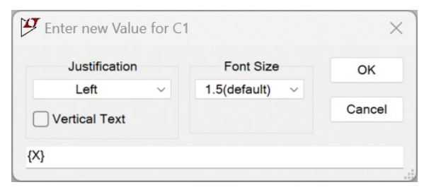
R1 is set to a fixed value of 1k, but C1 has been set to a variable X. The curly braces around X indicate to LTspice that X is a variable (Figure 2). To change a component value, right-click on the value, or right-click on the component symbol to bring up a more comprehensive view of the component properties.
A .PARAM directive in the schematic sets the value of X:
.PARAM X 0.1u
Using .STEP to Sweep Parameter Values
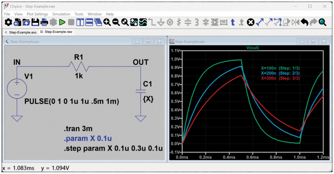
To convert this schematic to a simulation that steps through multiple values of X, comment out the .PARAM directive by shift + clicking on the directive. A commented directive shows as blue in the schematic.
Then, add a new directive by pressing. (or select Edit -> SPICE
Directive from the menu).
Step values can be specified as a list:
.STEP PARAM X LIST 0.1u 0.2u 0.3u
Step values can also be specified as a range:
.STEP PARAM X 0.1u 0.3u 0.1u
In the second syntax example, X is stepped as a range between 0.1u and 0.3u, in 0.1u increments. Both examples result in three values for X: 0.1u, 0.2u, and 0.3u. Further .STEP syntax examples can be explored in the .STEP section of the LTspice help manual.
Viewing Results and Adding a Step Legend
Run the simulation and plot OUT in the Waveform Viewer. There should be three unique waveforms plotted.
Right-click on the Waveform Viewer and select Notes &
Annotations -> Annotate Steps. Place the step legend in the
Waveform Viewer (Figure 3).
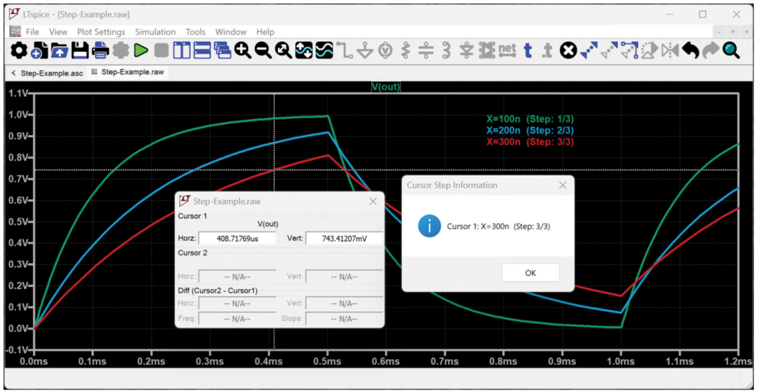
Click on the trace label, V(out), to display the cursor. Use the up and down arrow keys to toggle between step traces, and rightclick on the cursor to display the step information as illustrated in Figure 4.
Stepping Multiple Parameters in the Same Simulation
When a second .STEP directive is added to the schematic, LTspice will run a simulation for each possible combination of the two parameters. Explore this behavior by adding a second .STEP directive to sweep parameter Y and set the value of R1 to {Y}. An example sweep for Y is:
.STEP PARAM Y LIST 500 800 1.1k
Run the simulation and view the updated waveforms (Figure 5).
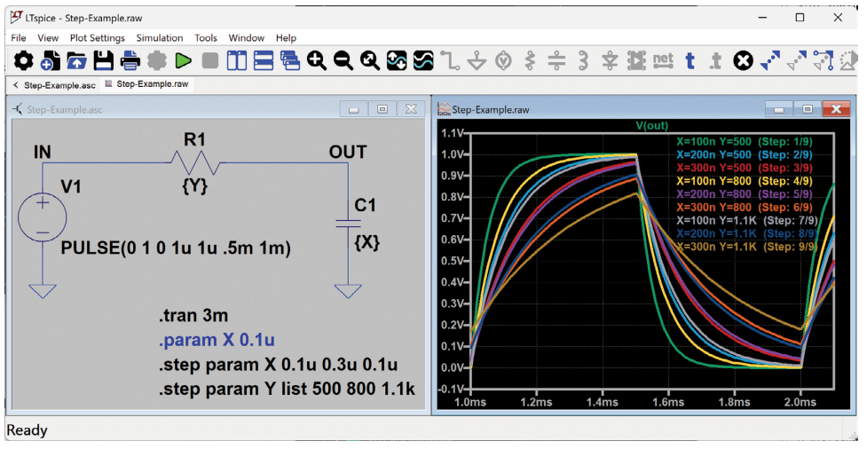
C1 and R1 each have three stepped values—so nine total simulations are run and displayed in the Waveform Viewer. The step legend is updated to show the parameter values used in each simulation run.
Using a Table to Step Through Parameter Value Combinations
Adding multiple .STEP directives is an effective way to sweep across a combination of scenarios—but a single .STEP directive combined with parameter tables enables the designer to take a more targeted approach, sweeping across a wider range of values with fewer simulations. An example circuit can be downloaded at Step-Table-Example.asc.
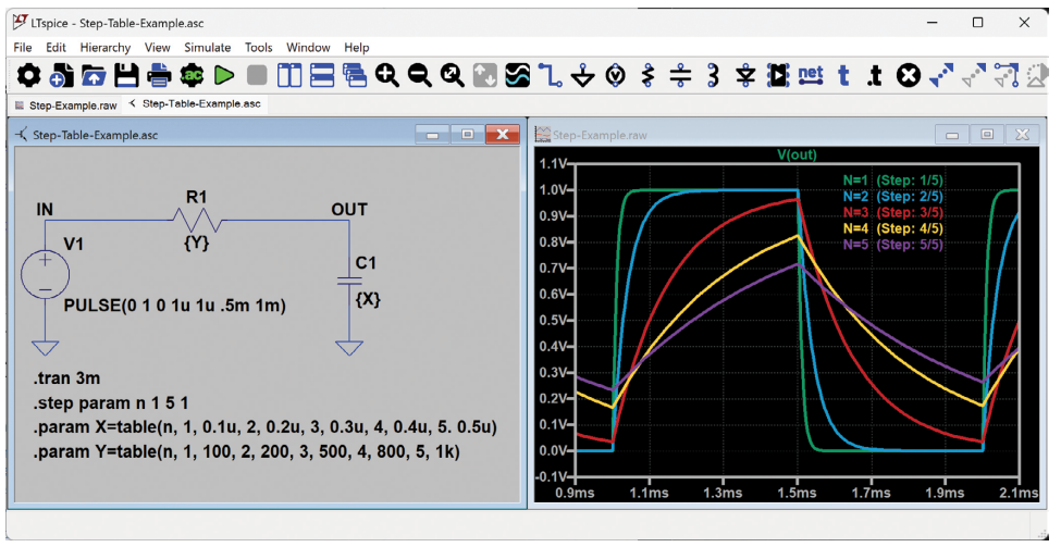
To step through a table of values, place a single .STEP directive that sweeps a parameter that represents a position in the table:
.step param n 1 5 1
combined with multiple .PARAM directives that define the parameter values as a table:
.param X=table(n, 1, 0.1u, 2, 0.2u, 3, 0.3u, 4, 0.4u, 5, 0.5u)
.param Y=table(n, 1, 100, 2, 200, 3, 500, 4, 800, 5, 1k)
This example results in five simulation runs that are summarized in Table 1.
| n | 1 | 2 | 3 | 4 | 5 |
| X | 0.1u | 0.2u | 0.3u | 0.4u | 0.5u |
| Y | 100 | 200 | 500 | 800 | 1k |
Stepping Through Models Using Strings
While is it not possible to create a .STEP parameter that holds string values, use the parameter table technique as an indirect way to step through string values. This is particularly useful when simulating across multiple device models such as diodes, transistors, or even imported SUBCKT models.
Similar to the previous example, combine a .STEP parameter that increments integers, and then use that parameter to map to a table of strings:
.step param n list 1 2 3.param bjtModel=table(n, 1, "2N2222", 2,
"2N3904", 3, "2N5089")
These directives illustrate how to step through multiple transistor models in LTspice.
Conclusion
Combining a .STEP directive with various analysis methods is a useful LTspice skill that enables deeper understanding of circuit behaviors and trade-offs.
About the Authors
Related to this Article
Resources
Solutions Bulletin & Brochure
Software and Simulation
Video
Design Tool


