LTspice How to: Importing Third-Party Models
Abstract
This article presents how to import third-party SPICE models into LTspice, step by step. The process of importing two different model types is covered: models implemented with .MODEL directives and models implemented with .SUBCKT blocks. The steps provided are intended to ensure maximum portability when sharing schematics with others.
Introduction
LTspice® makes it easy to create and simulate schematics quickly—sometimes the best starting point for hashing out a design is using ideal circuit elements. However, a circuit designer will need to improve the initial simple schematic with more realistic component models.
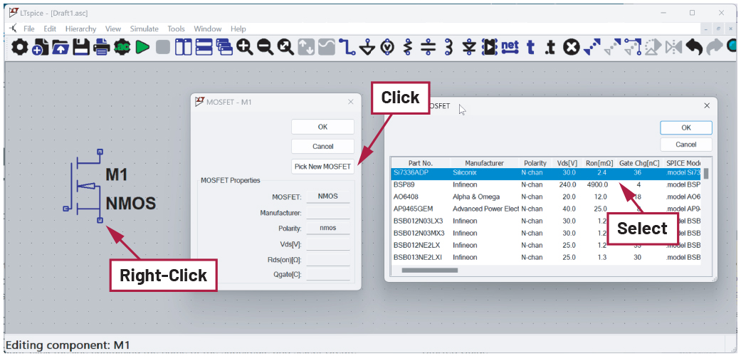
LTspice ships with an extensive collection of third-party manufacturer models. To use one of these models, simply right-click the component, then click the Pick… or Select button in the properties window and select one of the models listed. See Figure 1.

For devices that are not included in the LTspice component library, a model from an external source can be imported into LTspice. The steps required to accomplish this will vary depending on the device type and the model syntax.
There are two flavors of SPICE models: circuit behavior defined by a .MODEL directive and circuit behavior defined by a .SUBCKT directive. This article will provide guidance on importing both model types.
Note: If the imported model file is encrypted, it may be difficult to determine if the model was implemented with .MODEL or .SUBCKT directives. Contact the model vendor for support with encrypted models or post your issue on the LTspice EngineerZone® forum, someone in the EZ community might be able to help.
Each of the examples below is included in the LTspice-importing-third-party-models.zip file available for download here.
Importing a .MODEL Directive
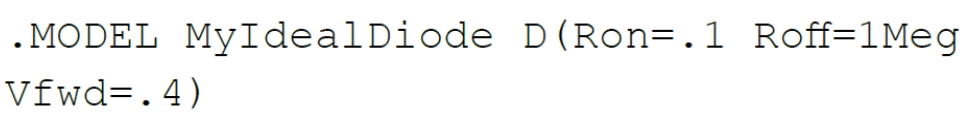
For a device that is modeled with a .MODEL directive, importing that model into LTspice is a fairly simple process. A .MODEL directive is a single line of code that contains the device name, device type, and parameter values for that model. Some models might be fairly simple and idealized, such as:
Manufacturer-provided models are going to be more complex. For example:
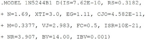
This example is a single line of code. The + character indicates to LTspice that this line is a continuation of the previous line.
See the help topic for the .MODEL directive in the LTspice manual for more information and related model parameters. In the LTspice menu, select Help > LTspice Help to access the LTspice manual.
Embedding a .MODEL Directive Directly in the Schematic
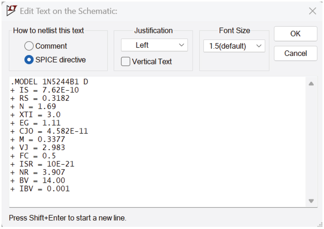
One option is to embed the .MODEL statement directly in the schematic. To add a SPICE directive to your schematic, select Edit > SPICE Directive from the menu, or type . (period) to bring up the Edit Text on the Schematic dialog. Copy and paste the .MODEL statement into the input field, click OK, and place the text on the schematic. See Figure 2.

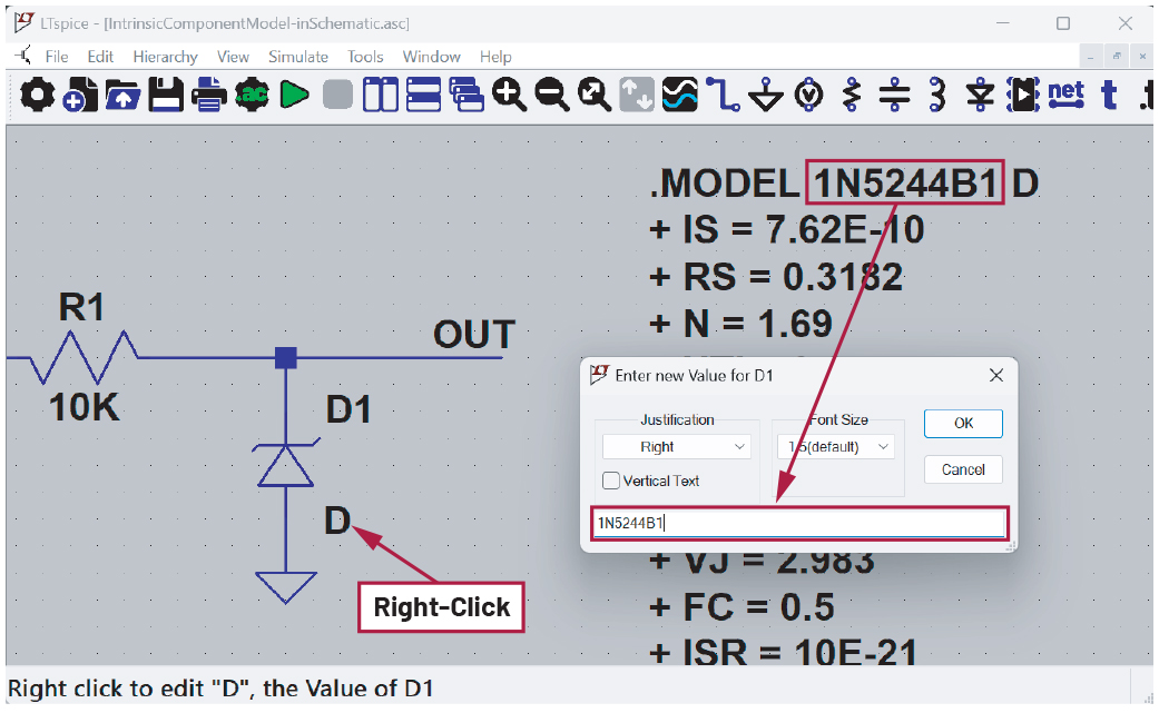
The next step is to add a component symbol to your schematic and ensure it points to your newly placed .MODEL directive. In this example, the 1N5244B1 is a Zener diode; place a Zener diode by selecting Edit > Component from the menu and select zener from the list. Click on the schematic to place the component symbol. Choose a generic symbol for this—do not select an ADI part. For example, if you need to import an op amp model, use the “opamp2“ component symbol rather than the AD822.
To make the connection between the component symbol and the .MODEL directive, right-click on the component value field. The default value is a placeholder value of “D” when the component is first placed. Enter the model name into the Enter New Value dialog. For this example, the model name is 1N5244B1. See Figure 3.

Refer to the schematic named intrinsic_model_embedded.asc in the zip file to explore this example further.
Importing a .MODEL Directive from a Text File
Another option for using a .MODEL directive is to have a separate text file that contains the model information. Keeping the model information in a file minimizes the clutter on the schematic; this is especially helpful if the model is long and complex.
The simplest way to accomplish this is to ensure that the model text file is in the same directory as the schematic and import the contents of the file with a .LIB directive. Add the .LIB directive by selecting Edit > SPICE Directive from the menu or typing . (period) to bring up the Edit Text on the Schematic dialog. If the model file is in the same directory as the schematic file, you can import the file by typing .LIB <filename>. For this example, the filename is 1N5244B.txt.
Make the link between the component and the model name using the method described in the previous section. In this example, the model name is 1N5244B1. See Figure 4.

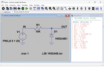
Note that the filename and the name of the model contained in the file may not be the same, as in this example. Additionally, a single file could have multiple model directives, so be sure to refer to the model name (and not the file name) in the component value.
Refer to the file named intrinsic_model_lib_file.asc to explore this example further.
Importing a .SUBCKT Model
The method of including a .SUBCKT model into your schematic is identical to what was required to include a .MODEL directive as previously described. Either copy and paste the contents of the model into the schematic as text using Edit > SPICE Directive, or use a .LIB statement to pull the contents of the subcircuit definition file into your schematic.
Placing and connecting a component symbol to your imported .SUBCKT model is a bit different than the steps that were required for an imported .MODEL directive and will be described in the following sections.
Using a .SUBCKT Model: Reusing an Existing Symbol
If the .SUBCKT model is a good match for one of the standard symbols already in the LTspice library, it’s light work to point one of those symbols to the imported .SUBCKT model.
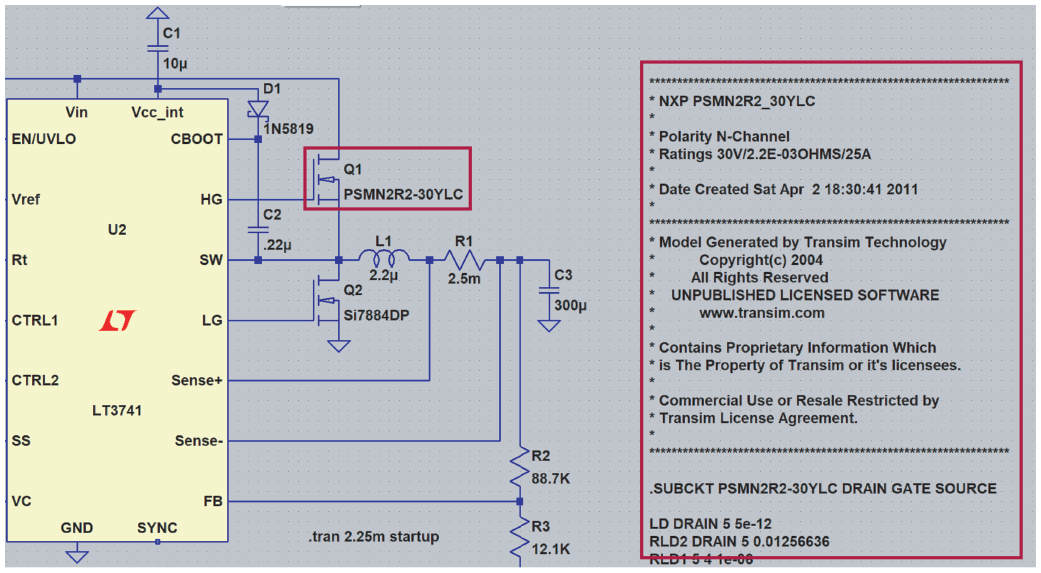
Using a .SUBCKT model and an existing schematic as a starting point, the steps needed to change the Si7884DP NMOS devices in this schematic with an imported model for the NXP PSMN2R2- 30YLC are detailed below. This model has been provided as a .SUBCKT file, PSMN2R2_30YLC.txt, with the following header information:

PSMN2R2-30YLC is the model name, followed by the pin names DRAIN, GATE, SOURCE. The order of the pin names matters—more on that later.
Since this is an NMOS device, it’s easiest to reuse the NMOS symbol in the LTspice library. Place an NMOS device by typing P (or selecting Edit > Component), selecting nmos from the list, clicking Place, and clicking on the schematic to place the NMOS symbol.
Figure 5 shows the example schematic where Q1 is pointing to an imported .SUBCKT model correctly. Notice the model name PSMN2R2-30YLC has been assigned to the value of Q1.

The example schematic already has Q1 set up to point to the imported PSMN2R2-30YCL model; the steps required to connect Q2 to this same model are detailed below. Open the subckt_with_included_symbol.asc example schematic to replicate the following steps.
To connect the .SUBCKT model to Q2, CTRL + right-click on Q2 to open the Component Attribute Editor. Change Value to PSMN2R2-30YLC, which matches the subcircuit name in the header of the model.
Important: Change the Prefix to X
Next, change the prefix to X, which is necessary when connecting a .SUBCKT model to a symbol. This is an additional step that was not required when importing a .MODEL directive.

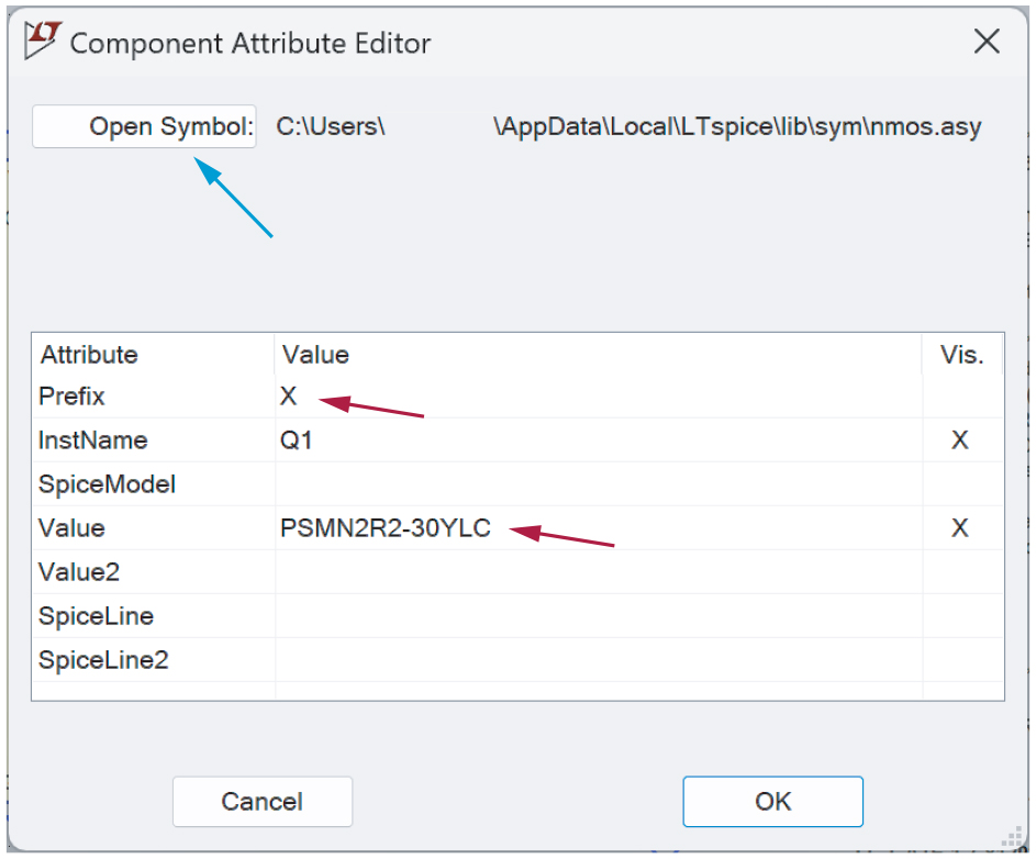
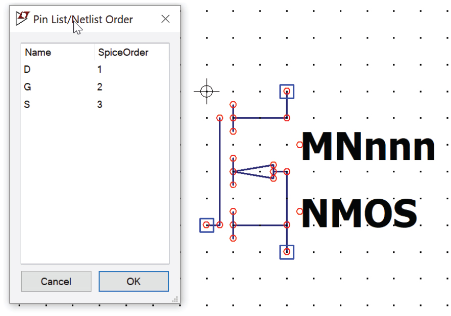
To confirm the pin order in the NMOS symbol in the LTspice library matches the imported model, click the Open Symbol button in this dialog. This will open the symbol editor. Select View > Pin Table to show the pin order (Figure 7). This confirms the pin order of DRAIN, GATE, SOURCE matches the order in the PSMN2R2-30YLC .SUBCKT definition.

Using a .SUBCKT Model: Creating a New Symbol
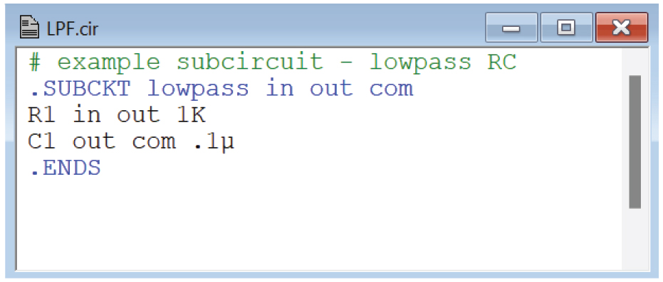
If a .SUBCKT model is not a good fit for an existing symbol, you can use LTspice to autogenerate a new symbol to go along with the subcircuit. LPF.cir is provided in the resources as a simple example. See Figure 8.

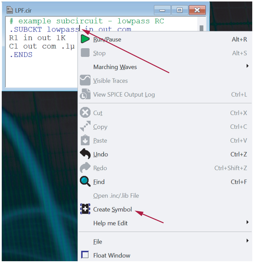
Right-click on the .SUBCKT name—lowpass in this example. Select Create Symbol and click Save. Be sure to save the new symbol to the same directory as the model file. See Figure 9.

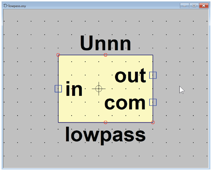
This will create an autogenerated symbol. This new symbol will open automatically in LTspice. See Figure 10.

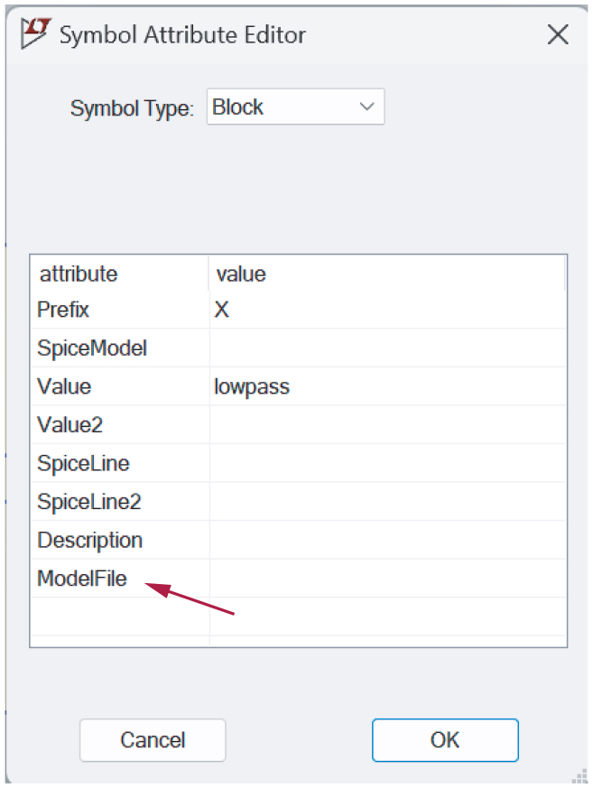
Remove the Hardcoded Model Path from the Symbol Attributes
With the new symbol open in LTspice, right-click on the symbol and select Attributes > Edit Attributes. Delete any path information that has been added to the ModelFile attribute to improve the portability of this symbol. Click OK, then click Save.

Editing a Newly Created Symbol
Now that there is a new symbol, you can edit it to better reflect the functionality of the model. Some simple tweaks with the Move tool (press M or select Edit > Move) will allow you to rearrange the pins to more sensible locations.
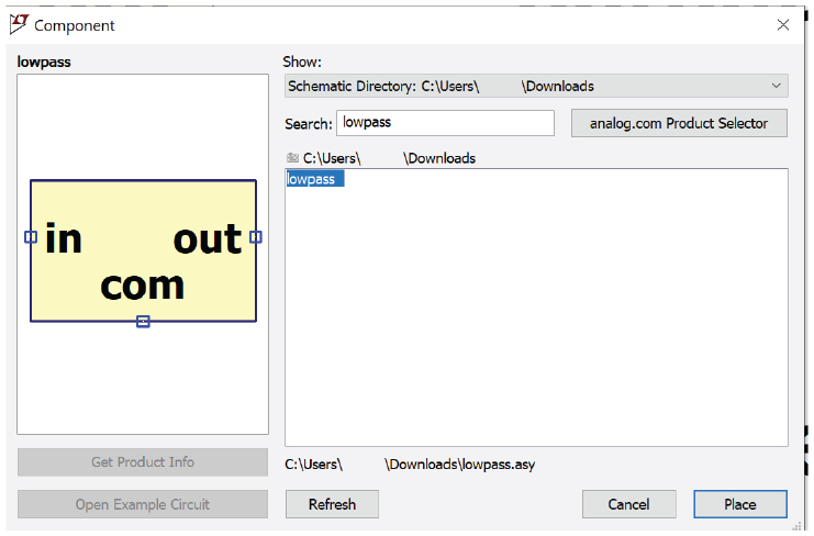
Placing the New Symbol in a Schematic
Ensure that the symbol file (.asy) and associated subcircuit file (.cir) are in the same directory as the schematic file (.asc). To place the new symbol in a schematic, type P (or Edit > Component) to open the Component dialog. Select Schematic Directory from the directory drop-down and select the newly created symbol (Figure 12). Click Place and click on the schematic to place the symbol.

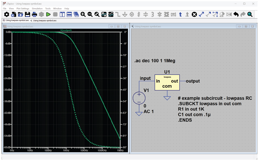
Be sure to include the .SUBCKT model in your schematic—either with the .LIB directive or as text directly in the schematic. See Figure 13 showing how to embed the .SUBCKT block directly in the schematic.

Sharing Simulation Files with Custom Symbols and Models
When sharing this schematic with others, ensure that all files including the schematic (.asc), the symbol (.asy), and any files pulled in with a .LIB directive are zipped up in the same directory.
Conclusion
There are many realistic device models already included in LTspice, but importing third-party models gives flexibility to incorporate a wide variety of models available from component vendors. The steps outlined in this article provide the guidance needed to build a working schematic that can be easily shared with others.
About the Authors
Related to this Article
Product Categories
Resources
Design Tool
Simulations
Software and Simulation


