Easy Automotive Power Supplies: Compact Regulator Produces Dual Outputs as Low as 0.8V from 3.6V–36V and is Unfazed by 60V Transients
Easy Automotive Power Supplies: Compact Regulator Produces Dual Outputs as Low as 0.8V from 3.6V–36V and is Unfazed by 60V Transients
Jan 1 2009
Introduction
The LT3509 dual channel step-down regulator operates over an impressively vast supply range of 3.6V to more than 36V, but its real distinguishing feature is its ability to handily protect both itself and downstream components from transient input voltages up to 60V. It accomplishes this by entering a safe shutdown mode when the supply exceeds 38V, such as load dump events in automotive electrical systems.
In a vehicle electrical system, overvoltage transients can occur when heavy loads are switched because the rapid change in current across the wiring inductance induces a high voltage. These transients are usually short in duration, from several microseconds to several milliseconds. Longer duration voltage surges can happen when the battery is disconnected and the alternator and its regulator must respond to reduce the energizing field in the rotor. This can take several hundred milliseconds, enough time to damage electronic components and subsystems.
The LT3509 protects itself and downstream systems from transient overvoltage events by shutting down for the duration of the event. For non-critical systems, that is all the protection that is needed, as long as power is restored relatively quickly. For critical systems that require full functionality during a transient event, a supercapacitor ride-through circuit can continue to provide hold-up power (see Linear Technology Design Note 450 or the cover article from the September 2008 issue of Linear Technology magazine). This article shows a circuit that allows powered systems to ride-through transients without requiring a reset.
A Little About the LT3509
The LT3509 integrates popular high voltage features into a compact dual supply solution for a wide range of applications. Each of two channels can produce up to 0.7A at an output voltage as low as 0.8V to within a half a volt of the input supply. It has integrated BOOST diodes and internal compensation to minimize the component count and the required board area. Robust short-circuit protection is also provided using catch diode current sensing. The ride-through feature is particularly useful in automotive applications, as is the wide operating frequency range of 300kHz to 2.2MHz and the ability to synchronize to an external reference clock. The switching frequency can be chosen or externally driven to meet stringent EMI requirements.
Riding Through Supply Transients
One way to reduce the ride-through energy storage requirements is to provide a FAULT signal to the powered systems so that that they can enter a low power state for the duration of the event. For example a microcontroller could enter a HALT state, digital circuitry could stop or reduce the clock frequency, displays could be blanked and audio circuits muted. This reduces the power draw to a minimum so that the output voltages can be maintained with relatively small electrolytic capacitors.
The LT3509 itself does not provide a dedicated logic signal to indicate that an overvoltage event has occurred but it is possible to detect the event by monitoring the RUN/SS pins. These pins are pulled low by an internal device whenever an overvoltage condition exists, but as they were not intended to drive logic directly a small interface circuit is required as shown in Figure 1. The RUN/SS pins are pulled up to approximately 3.0V by an internal 1µA pull-up in normal operation and are pulled to about 0.6V during a fault condition. This circuit has a switching threshold of around 1.4V and draws very little input current. The circuit operates at a very low current and the transistors were carefully selected—generic types may not give satisfactory performance. Q1’s collector must be supplied from VIN with a resistor divider as shown. If connected to VOUT, the collector base junction will be forward biased at power-up and thus preventing the LT3509 from starting up. The resistor divider keeps the collector-emitter voltage of Q1 below its breakdown voltage.

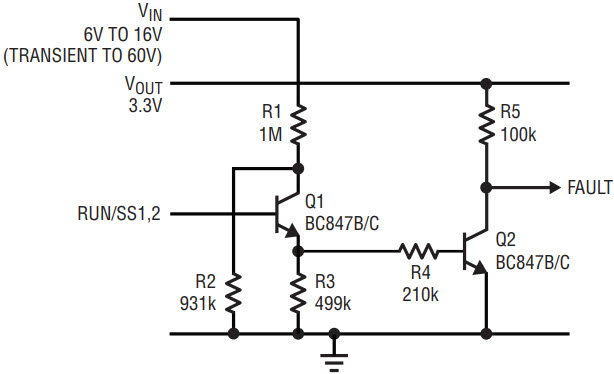
Figure 1. LT3509 RUN/SS to FAULT signal interface.
Automotive Accessory Supply 3.3V and 1.8V with Ride-Through Capability
The schematic in Figure 2 shows a typical application for a dual supply system requiring 3.3V and 1.8V rails, such as a radio or satellite navigation system. The goal is to maintain support for a ride-through capability described in the introduction where the output voltage is maintained just long enough for the powered circuitry to enter a low current state. The key features are that it includes the fault indication circuit of Figure 1 and the standard 10µF ceramic output capacitors C5 and C8 are augmented with 1000µF electrolytic capacitors C4 and C9. The ceramic capacitors should still be used to control high frequency ripple as they have much lower ESR than the electrolytic types.

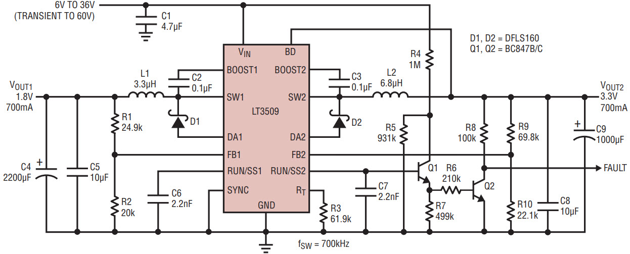
Figure 2. 12V auto battery to 3.3V and 1.8V with hold-up capacitors and FAULT indicator.
The operating frequency is kept low to ensure that the 1.8V channel operates in fixed frequency mode at the normal operating voltage. The output capacitors have to support the output voltage while the regulator shuts off due to an overvoltage ride-through event. They must also supply the full load current for the time taken from the start of the overvoltage event until the load is put in a powered down state. The delay time from the overvoltage condition until the fault signal is asserted is dependent on the capacitor value on the RUN/SS pin. With the component values in the example circuit this is approximately 40µs. To this must be added any time for the powered circuit to shut down. The voltage droop during this time can be calculated from ∆V = I • t/C. So for 700mA, 40µs and 1000µF gives ∆V = 0.7A • 40µs/1000µF = 28mV.
Once the powered circuits have shut down, the droop rate depends on the residual current draw and the duration of the transient event. In an ideal case the system power should reduce to a few µA in which case the dominant current draw will be from the feedback divider, which in the example circuit takes around 37µA. Using the same equation, for a 400ms event, the droop during the transient is: ∆V = 40µA • 0.4s/1000µF = 16mV. Clearly the biggest droop occurs during the initial loss of power.
One last thing to consider is what happens when the transient is finished and normal operation resumes. The FAULT signal de-asserts as soon as the RUN/SS pin rises above the threshold, but the regulator is not able to deliver full current until the RUN/SS pin reaches approximately 2V. It may be necessary to create a small delay, by software perhaps, from the time FAULT goes away until full current is demanded.
The LT3509 prevents inrush currents at start-up with a current limiting soft-start feature, which allows the available output current to ramp up slowly. Both the peak current limit and the valley current limit (the one sensed through the catch diodes) are controlled by the voltage on the RUN/SS pins, so as capacitors C6 and C7 charge up, the output current slowly increases to its normal maximum value. An example of the soft-start characteristic is shown in Figure 3.

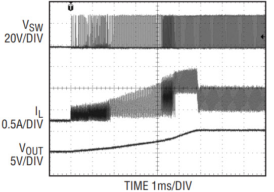
Figure 3. Soft-start waveforms.
Demonstration and Test Results
The ride-through performance the application of Figure 1 is tested using the setup shown in Figure 4. A switched supply produces either a normal input or an overvoltage transient. The output is connected to an active load circuit with ON/OFF controlled by the FAULT signal. Figure 5 shows the start of the overvoltage event on a fast time base to show the step that occurs as the regulator shuts off, but before the load is reduced. Figure 6 shows the entire 400ms transient and the droop that happens when there is no output but also very little load. Figure 7 shows the end of the event on an expanded timescale.

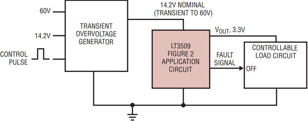
Figure 4. Test and demonstration set-up.

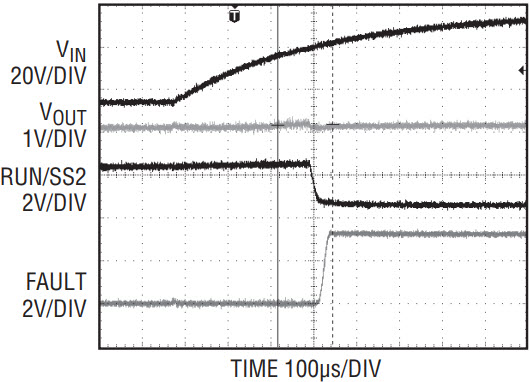
Figure 5. Transition to ride-through mode.

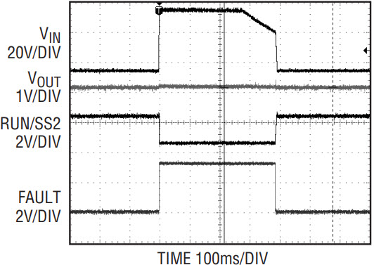
Figure 6. Complete ride-through event.

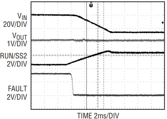
Figure 7. End of ride-through event.
Conclusion
Overvoltage transients are a fact of life in automobile and industrial power systems. The LT3509, combined with a small, low cost capacitor, can be used to both protect components from overvoltage transients and allow the downstream systems to ride through the event without having to completely reset. It is possible to ride through an overvoltage transient of even several hundred milliseconds, provided a brief interruption of service can be tolerated.
About the Authors
Related to this Article
Products
Latest Media 21