
MAXREFDES1160


Overview
Design Resources
Description
The MAXREFDES1160 is a 5V supplied, 2.75kVRMS, full-duplex and 500kbps isolated RS-485 module using the MAX14853. This reference design demonstrates how to build an isolated RS-485 module with a low-cost transformer to provide isolated power. A transformer from HanRun, the HR600755, is used in this design. The power supply on the reference design is derived from a single 5V source. Connect the design board to a USB port or connect an external supply from VDDA to GNDA to provide 5V power supply on the logic side (A). The integrated push-pull transformer driver and external transformer (TX1) generate an isolated supply for powering the isolated side (B) of the board.
The MAX14853 isolated RS-485/RS-422 transceiver provides 2750VRMS (60s) of galvanic isolation between the cable-side (RS-485/RS-422 driver/receiver-side) and the UART-side of the module. This device allows for robust communication up to 500kbps. The MAX14853 includes an integrated 450kHz transformer driver for power transfer to the cable-side of the transceiver using an external transformer. An integrated LDO provides a simple and space-efficient architecture for providing power to the cable-side of the IC. The MAX14853 includes one drive channel and one receive channel. The receiver is ¼-unit load, allowing up to 128 transceivers on a common bus. Integrated true fail-safe circuitry ensures a logic-high on the receiver output when inputs are shorted or open. Undervoltage lockout disables the driver when cable-side or UART-side power supplies are below functional levels. The driver outputs and receiver inputs are protected from ±35kV electrostatic discharge (ESD) to GNDB on the cable-side, as specified by the Human Body Model (HBM).
Parts Used
Details Section
The MAXREFDES1160 is a 5V supplied, 2.75kVRMS, full-duplex and 500kbps isolated RS-485 module using the MAX14853. This reference design demonstrates how to build an isolated RS-485 module with a low-cost transformer to provide isolated power. A transformer from HanRun, the HR600755, is used in this design. The power supply on the reference design is derived from a single 5V source. Connect the design board to a USB port or connect an external supply from VDDA to GNDA to provide 5V power supply on the logic side (A). The integrated push-pull transformer driver and external transformer (TX1) generate an isolated supply for powering the isolated side (B) of the board.
The MAX14853 isolated RS-485/RS-422 transceiver provides 2750VRMS (60s) of galvanic isolation between the cable-side (RS-485/RS-422 driver/receiver-side) and the UART-side of the module. This device allows for robust communication up to 500kbps. The MAX14853 includes an integrated 450kHz transformer driver for power transfer to the cable-side of the transceiver using an external transformer. An integrated LDO provides a simple and space-efficient architecture for providing power to the cable-side of the IC. The MAX14853 includes one drive channel and one receive channel. The receiver is ¼-unit load, allowing up to 128 transceivers on a common bus. Integrated true fail-safe circuitry ensures a logic-high on the receiver output when inputs are shorted or open. Undervoltage lockout disables the driver when cable-side or UART-side power supplies are below functional levels. The driver outputs and receiver inputs are protected from ±35kV electrostatic discharge (ESD) to GNDB on the cable-side, as specified by the Human Body Model (HBM). Table 1 shows an overview of the design specification.
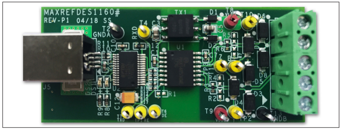
This document describes the hardware shown in Figure 1. The isolated RS-485 communication module has been built and tested.
| PARAMETER | SYMBOL | MIN | MAX |
| Supply Voltage | VDDA | 3.3V | 5.5V |
| Cable-side LDO Supply Voltage Input | VLDO | 3.18V | 14V |
| LDO Output Voltage B Side | VDDBO | 3.3V | |
| USB Input Voltage | VUSB | 5V | |
| Standby Current | ISTANDBY | 18mA | |
| Withstand-Isolation Voltage | VISO | 2.75kV for 60s | |
| Maximum Data Rate | DRMAX | 500kbps | |
| Temperature Range | TOPERATION | -40°C | +85°C |
The MAXREFDES1160 uses the MAX14853 to provide 2.75kVRMS (60s) of galvanic isolation between the RS-485/RS-422 cable side of the transceiver and the UART side. Both data and power can be transmitted across the isolation barrier in the MAX14853. To achieve data isolation, integrated capacitive isolation allows data transmission between the UART and cable sides of the transceiver. To achieve power isolation, the MAX14853 features an integrated-transformer driver to drive an external center-tapped transformer that can transfer operating power from the UART side across the isolation barrier to the cable side. In this reference design, the primary side of an external transformer connects to the MAX14853 transformer driver outputs to provide a completed full-duplex RS-485 isolation solution.
Transformer Selection
With the MAX14853 transformer driver, we can save the external isolated power supply. Select a transformer with an ET product greater than or equal to the ET of the driver to ensure that the transformer does not enter saturation. E is the voltage applied to the transformer, and T is the maximum time applied during one cycle. Calculate the minimum ET product for the primary transformer as follows:

where VMAX is the worst-case maximum supply voltage on VDDA, and fMIN is the minimum frequency at that supply voltage. In this design where VMAX = 5.5V and fMIN = 350kHz, the required minimum ET product is 7.9Vµs.
The transformer isolation level should be equal or greater than the isolation level of the MAX14853. We used a 5V power supply on the logic-side, so the transformer turn ratio is 1:1.1 or 1:1. In this reference design, we chose the HanRun HR600755 low-cost transformer.
Passive Components on the RS-485 Line
There are two 120Ω termination resistors on the board as end-of-the-line transceivers: R3 is connected between the Y and Z driver outputs, and R6 is connected between the A and B inputs. Pullup and pulldown resistors are used on the receiver inputs to guarantee a known state in the event that all nodes on the bus are in receive mode or the cable becomes disconnected. The exact values for these resistors vary with the application. Pads are provided for the pullup resistors (R2, R5) and pulldown resistors (R4, R7), although the use of these resistors is optional.
The MAX14853 features true fail-safe receiver inputs, which ensure that RXD is high when the receiver inputs are shorted, open, or connected to an idle bus. We added TVS diodes between the A-B, A-GNDB, and B-GNDB lines to reinforce protection.
USB to UART Design
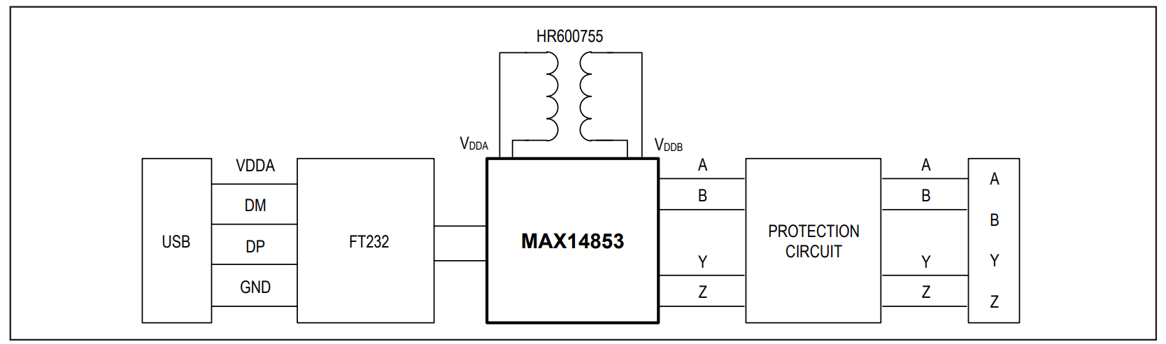
The FTDI™ USB to serial UART interface, FT232RL, is used in this design to perform RS-485 communication. The control signal CBUS2 is connected to the DE and RE pins on the MAX14853. For the full-duplex RS-485, the transmitter driver and receiver use two differential lines for communication, so transmitting and receiving between the host and slave can perform simultaneously.
Figure 2 shows the system block.
Documentation & Resources
-
MAXREFDES1160 Design Files3/3/2021ZIP2 M
Support & Training
Search our knowledge base for answers to your technical questions. Our dedicated team of Applications Engineers are also available to answer your technical questions.