
TMC5262-EVKIT


Overview
Features and Benefits
- Highly Integrated 2-Phase Stepper Motor Driver SoC
- 4.5V to 65V DC Voltage Range
- Up to 4.25ARMS and 6AFS Current Capability
- Integrated 65V H-Bridges with low RDS (ON) (HS + LS): 0.08Ω (typ) (TA = 25°C)
- Integrated Lossless Current Sensing (ICS)
- Advanced Motion and Motor Control
- EightPoint Ramp for Minimized-Jerk Motion
- 256-Microsteps
- StealthChop+, StallGuard+, CoolStep+, μDcStep
- SpreadCycle, StallGuard2, CoolStep
- Passive Braking and Freewheeling Modes
- Flexible Control and Feedback Interfaces
- SPI for Configuration, Control, and Diagnostics
- STEP/DIR and Incremental Encoder Interfaces
- Reference Switch Inputs
- Integrated Protection and Diagnostics
- RT-OCSI
Product Details
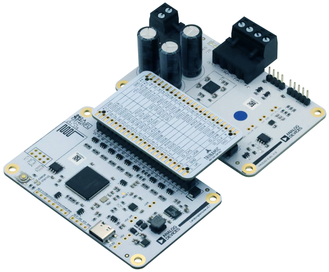
The TMC5262-EVKIT includes the TMC5262-EVAL board together with the Eselsbruecke and Landungsbruecke interface boards as part of the ADI Trinamic™ TMCL ecosystem.
The TMC5262 is a smart, high-performance, single-axis 2-phase stepper motor controller and driver IC designed for NEMA 17, NEMA 23, and NEMA 24 stepper motor applications. The TMC5262 features two fully-integrated 65V H-bridges rated for up to 4.25ARMS (6AFS) motor current and lossless integrated current sensing (ICS), eliminating the need for external MOSFETs and current sense resistors.
The integrated position and velocity controller, together with the flexible EightPoint ramp generator, automatically positions the motor and minimizes jerk in motion profiles. Advanced motion control technologies such as StealthChop+™, StallGuard+™, CoolStep+™, µDcStep, SpreadCycle, StallGuard2™ and CoolStep™, combined with 256-microsteps operation, further improve motion quality, efficiency, and motor performance.
The device supports SPI, STEP/DIR, incremental encoder, and reference switch interfaces, while extensive diagnostic, monitoring, and protection functions, including real-time on-chip scope interface (RT-OCSI), simplify system development and debugging.
The TMC5262-EVAL board enables evaluation of the TMC5262 using TMCL-IDE or the PyTrinamic™ Python package.
Applicable Parts
Getting Started
Required Items
- TMC5262-EVAL (included)
- Landungsbruecke board (included) with the latest TMC-EvalSystem firmware
- Eselsbruecke board (included)
- A compatible motor (for example, a Qmot stepper motor)
- Power supply (4.5V to 65V; power connector included in the kit)
- Cables to interface the motor, encoders, and the power supply
- USB-C data cable
- PC with the latest TMCL-IDE (the integrated development environment for ADI Trinamic™ modules)
- TMC5262 data sheet
Precautions
- Follow the safe electrostatic discharge (ESD) practices.
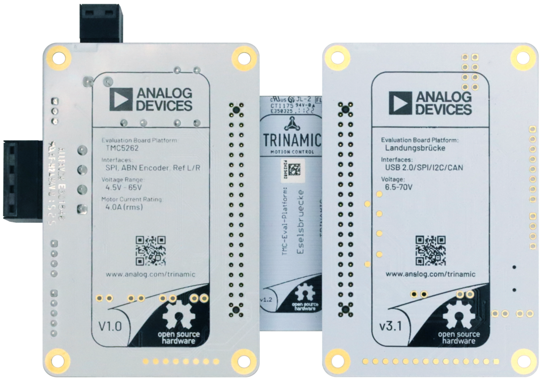
- Ensure the working area is nonconductive to prevent shorting of exposed pins on the underside of circuit boards.
- Do not exceed the board’s maximum rated supply voltage.
- Do not connect or disconnect the motor while the board is powered.
- Make sure that the used board, cables, and motor are in a good state before using them.
- Ensure to use the appropriate protection while working with high voltages. In some countries, voltages higher than 50V are considered dangerous.
- Do not touch the power stage section of the board during operation as it can get hot.
- Do not touch the IC on the board.
Connecting the Peripherals
To connect the peripherals and first power on, do the following steps:
- Unpack the Landungsbruecke, Eselsbruecke, and TMC5262-EVAL boards and inspect each board for shipping damage. The motor-output and power-supply connectors, along with pin-header jumpers are preinstalled.
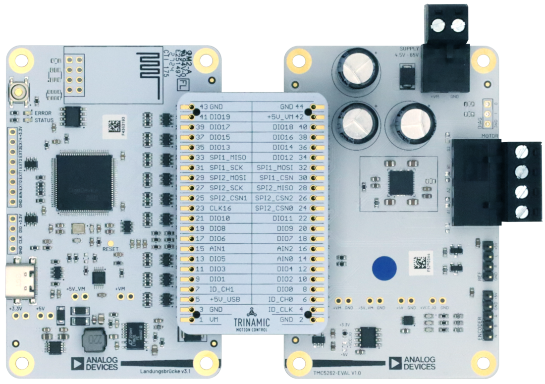
- Interface the TMC5262-EVAL with the Landungsbruecke through the Eselsbruecke bridge board, as shown in Evaluation Kit Photo. While connecting the boards, both the Landungsbruecke and the TMC5262-EVAL must not be powered. Make sure that every pin in the connector is connected to its corresponding header. The working area is nonconductive to prevent shorting of pins on the backside of the boards.
- Plug the selected motor to connector J203, which is labelled as MOTOR on the board’s silkscreen (Figure 4). Observe the correct order of the motor phases.
- (Optional) Plug the ABN Encoder to pin header J204, which is labelled as ENCODER on the board’s silkscreen (Figure 4).
- Connect the Landungsbruecke board to the computer through a USB cable.
- Plug the power supply cable to Connector J202, which is labelled as SUPPLY on the board’s silkscreen (Figure 4). Make sure that the power supply is off and the polarity of the cables is correct before plugging it to the board.
Note: Voltages above 50V are considered dangerous in some countries. Keep the work area clean and do not touch the board while powered on. Keep in mind that the power stage section of the board can get hot during operation.
The board is now ready to proceed to the next steps. Continue with the following section, but do not turn on the power supply yet.
Documentation & Resources
-
TMC5262-EVKIT Gerber Files3/16/2026ZIP576 KB