


Overview
Features and Benefits
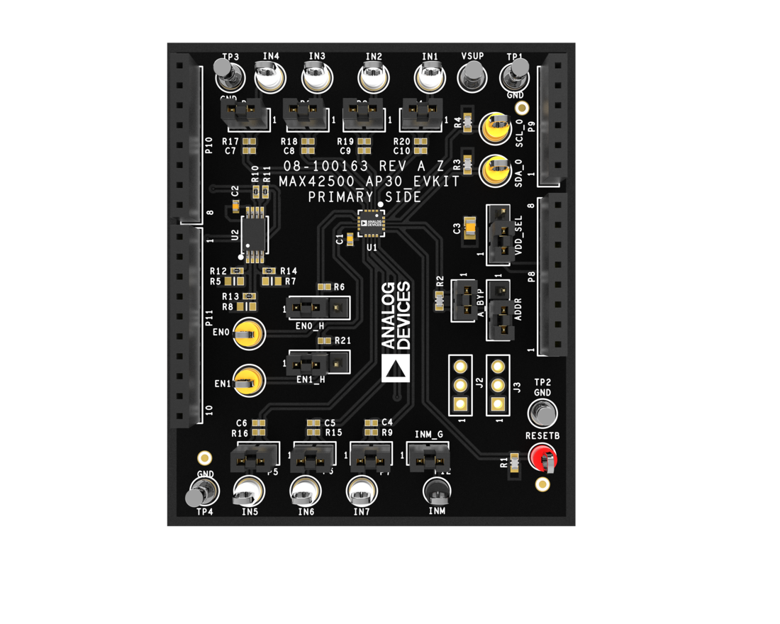
- Easy Access Inputs
- IN1-IN7, with INM Pin for Remote Ground of IN6 and IN7
- ADDR Pin and Jumper for Different I2C AddressSettings
- EN0 and EN1 Jumpers for Easy Configuration
- RC Footprints on Monitoring Pins, with Jumpers forResistor Bypass
Product Details
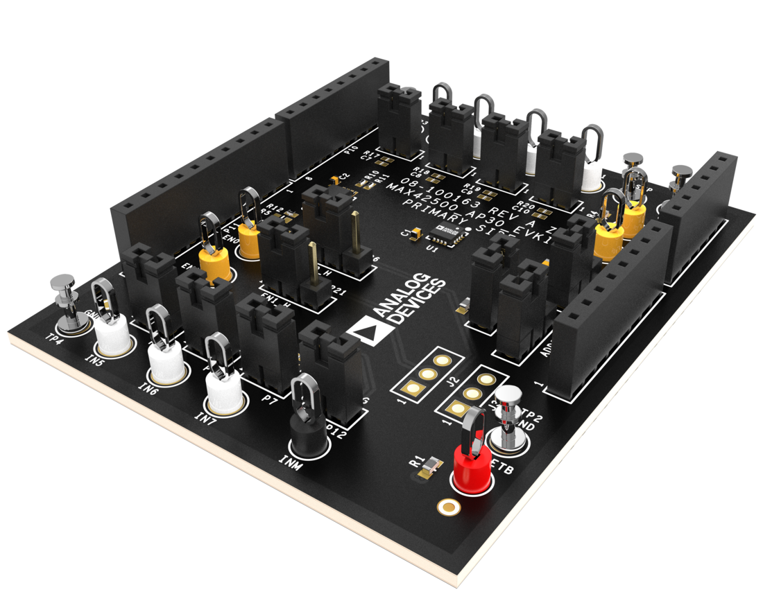
The MAX42500 evaluation kit (EV kit) is a fully assembled and tested application circuit designed for the MAX42500 seven‑input industrial power system monitor. The board provides accessible test points for the seven monitored voltages, reset output, and other input signals. The evaluation board connects directly to the SDP Arduino®‑compatible shield connector, allowing the MAX42500 to interface directly with the SDP controller, which serves as the main system controller.
This user guide contains the MAX42500 ACE plugin, which provides a user-friendly graphical user interface (GUI) that streamlines the evaluation and testing of the MAX42500 evaluation board or EV kit. It allows engineers and system developers to interact with the device without the need for extensive programming knowledge or custom firmware. By simplifying configuration and offering real-time performance insights, the software accelerates the understanding of the device’s behavior and suitability for the intended application, ultimately reducing the overall evaluation time.
Analog Devices’ Analysis, Control, Evaluation (ACE) software is available for use with the EV kit and can be downloaded from ADI’s website.
Applicable Parts
Getting Started
Hardware Requirements
- MAX42500 EV kit
- SDP-K1 evaluation board
- Type-C USB connector
- PC/Laptop
- Adjustable DC supplies
Software Requirements
- ACE installer
- MAX42500 ACE plugin
- SDP EEPROM programmer
Documentation & Resources
-
MAX42500EVKIT User Guide: Evaluates: MAX42500 (Rev. 1)6/30/2026PDF1 MB
-
MAX42500EVKIT Gerber Files6/30/2026ZIP1 MB