User Guide
Rev.
0
1
View All
Overview
Features and Benefits
- Easy Evaluation of the MAX14918A
- Robust Operation with a Wide Range of Output Voltages and Load Conditions
- LED Indication of Fault and Reverse-Current Detection Conditions
- Robust Design at Field Outputs
- Internal Inductive Fast Demagnetization
- Short-Circuit Protection
- Up to ±1.2kV IEC 61000-4-5 Surge Protection
- Up to ±8kV IEC 61000-4-2 Contact ESD Protection
- Up to ±25kV IEC 61000-4-2 Air-Gap ESD Protection
- Resistor-Settable Load Current Limit
- 2x Inrush Load Current Option for 10ms (min)
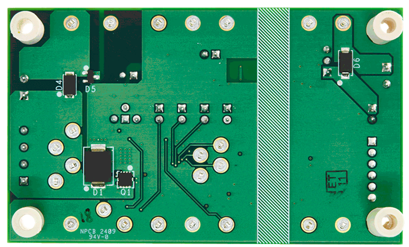
- Onboard MOSFET for Output Reverse-Current Protection
- Optional Onboard Isolated 5V to Power the MAX14918A from the Logic-Side Supply
- Galvanic Power and Data Isolation Using ADuM6028 and ADuM340E
- Proven PCB Layout
- Fully Assembled and Tested
- RoHs Compliant
Product Details
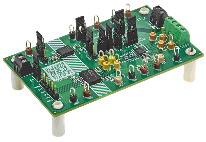
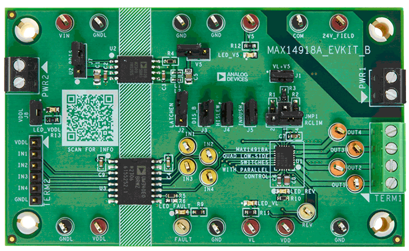
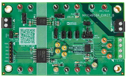
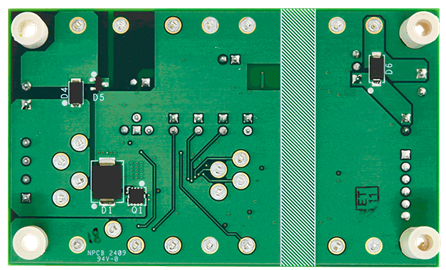
The MAX14918A evaluation kit (EV kit) provides a proven design to evaluate the MAX14918A, parallel controlled quad low-side switches with reverse-current detection. The MAX14918A EV kit features an isolated power and digital interface to provide pin-level control of the four low-side switches in the MAX14918A. The EV kit also features reverse-current protection to prevent damage caused by miswiring faults at output and COM return terminals. The EV kit comes with the MAX14918AATG+ in a 4mm x 5mm 24-pin TQFN package, installed as U1.
Documentation & Resources
-
MAX14918AEVKIT User Guide (Rev. 0)6/28/2024PDF821 K
-
MAX14918AEVKIT Gerber Files6/28/2024ZIP2 M
