EVAL-LTC3313EV-MULTI-AZ
User Guide
Rev.
0
1
View All
Overview
Features and Benefits
- EVAL-LTC3313EV-MULTI-AZ evaluation board
- Transient circuit included for load transient evaluation
- RT pin pull-up option for external clock synchronization
Product Details
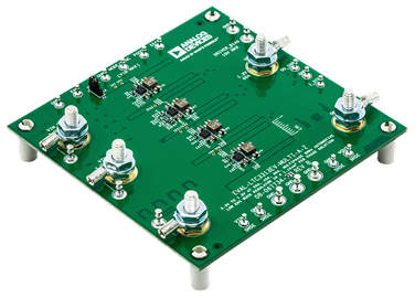
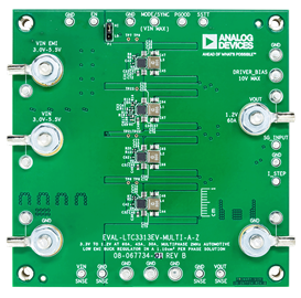
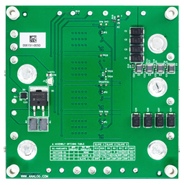
The EVAL-LTC3313EV-MULTI-AZ features the LTC3313, a 15 A, low-voltage, synchronous step-down Silent Switcher®, operating as a multiphase 2 MHz, 3.0 V to 5.5 V input, 1.2 V buck regulator. The EVAL-LTC3313EV-MULTI-AZ has three build options to provide 2-phase 30 A, 3-phase 45 A, or 4-phase 60 A output solutions. The LTC3313 supports adjustable output voltages from 0.5 V to input voltage (VIN) and operating frequencies from 500 kHz up to 5 MHz in multiphase operation.
All phases of EVAL-LTC3313EV-MULTI-AZ operate in forced continuous mode at 2 MHz switching frequency (fSW). The LTC3313 can also synchronize to an external clock using a MODE/SYNC turret when the RT pin of the main phase is pulled up to the VIN pin.
The EVAL-LTC3313EV-MULTI-AZ also has an electromagnetic interference (EMI) filter to reduce conducted EMI. This EMI filter can be included by applying the input voltage at the VIN EMI terminal.
Figure 4 shows the efficiency of the circuit with a 3.3 V input for all three build options.
An on-board transient circuit is included to measure fast transient performance.
The LTC3313 data sheet gives a complete description of the part, operation, and application information. The data sheet must be read in conjunction with this user guide. The LTC3313 is assembled in a 3 mm × 3 mm LQFN package with exposed pads for low thermal resistance. The layout recommendations for low EMI operation and maximum thermal performance are available in the LTC3313 data sheet.
Applicable Parts
Getting Started
- A DC voltage source
- An electronic load
- A multimeter


