
EVAL-ADL7075


Overview
Features and Benefits
- 4-layer Rogers 4350B evaluation board
- End launch, 2.9mm RF connectors
- Through calibration path (depopulated)
Product Details
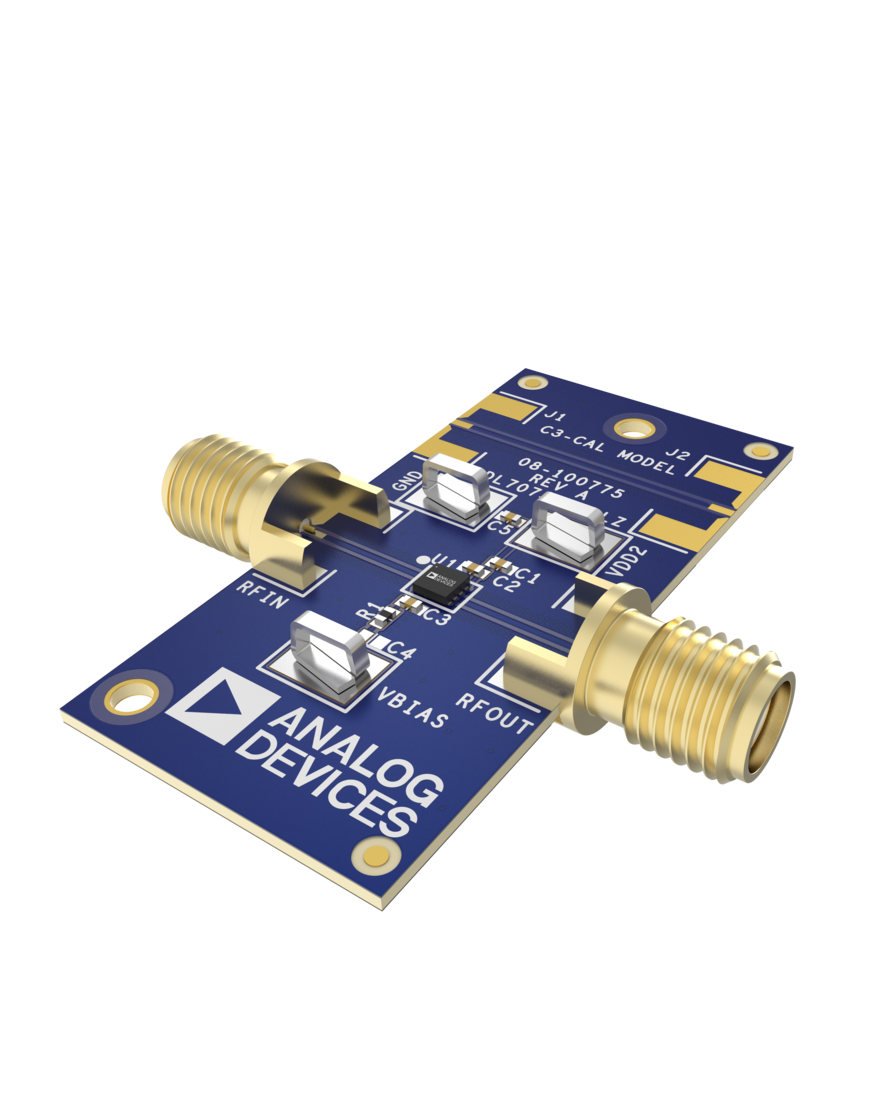
The ADL7075-EVALZ is a 4-layer printed circuit board (PCB) fabricated from 10mil thick, Rogers 4350B, and copper clad.
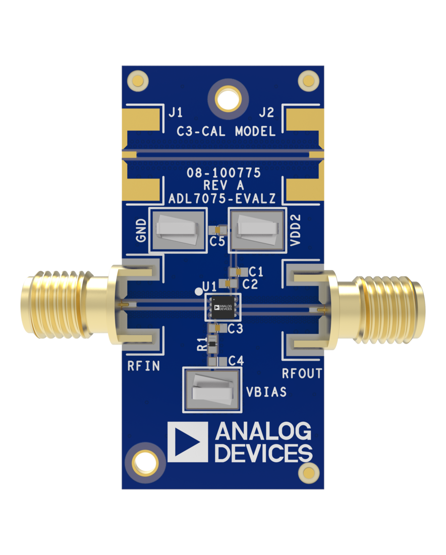
The RFIN and RFOUT ports on the ADL7075-EVALZ are populated with 2.9mm, female coaxial connectors, and the corresponding RF traces have a 50Ω characteristic impedance. The ADL7075-EVALZ is populated with components suitable for use over the entire −55°C to +125°C operating temperature range.
To calibrate board trace losses, a through calibration path, THRUCAL, is provided between the J1 and J2 connectors. J1 and J2 must be populated with RF connectors to use the through calibration path. For the through calibration path performance, see Figure 4 and Table 1.
Access the ADL7075-EVALZ ground path and the VDD pin through the surface-mount technology (SMT) test point connectors, GND, and VDD. A supplementary test point for VBIAS is included for simple access on the RBIAS pin (for the test point locations, see Figure 6).
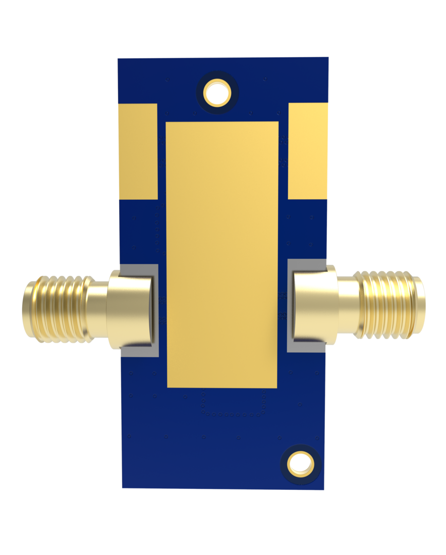
The RF traces on the ADL7075-EVALZ are 50Ω, grounded, coplanar waveguide. The package ground leads and the exposed pads connect directly to the ground plane. Multiple vias connect the top and bottom ground planes with particular focus on the area directly beneath the ground paddle to provide adequate electrical conduction and thermal conduction.
The power-supply decoupling capacitors on the ADL7075-EVALZ represent the configuration used to characterize and qualify the device.
Full specifications on the ADL7075 are available in the ADL7075 data sheet available from Analog Devices, Inc., and must be consulted with this user guide when using the ADL7075-EVALZ evaluation board.
Applicable Parts
Getting Started
EQUIPMENT NEEDED
- RF signal generator
- RF spectrum analyzer
- RF network analyzer
- 5V, 500mA power supply
- External bias tee or external DC block
Documentation & Resources
-
EVAL-ADL7075 Gerber Files7/29/2026ZIP2 MB