


Overview
Features and Benefits
- Fully functional Li-Ion cell formation and testing similar to real-world manufacturing equipment
- Ability to charge and discharge batteries under constant current and constant voltage control
- Energy recycling from discharging battery into a dc bus
- Full featured system evaluation board based on the AD8452
- PC software for control and monitoring of system parameters
- Compatible with the System Demonstration Platform, SDP-S (EVAL-SDP-CS1Z)
Product Details
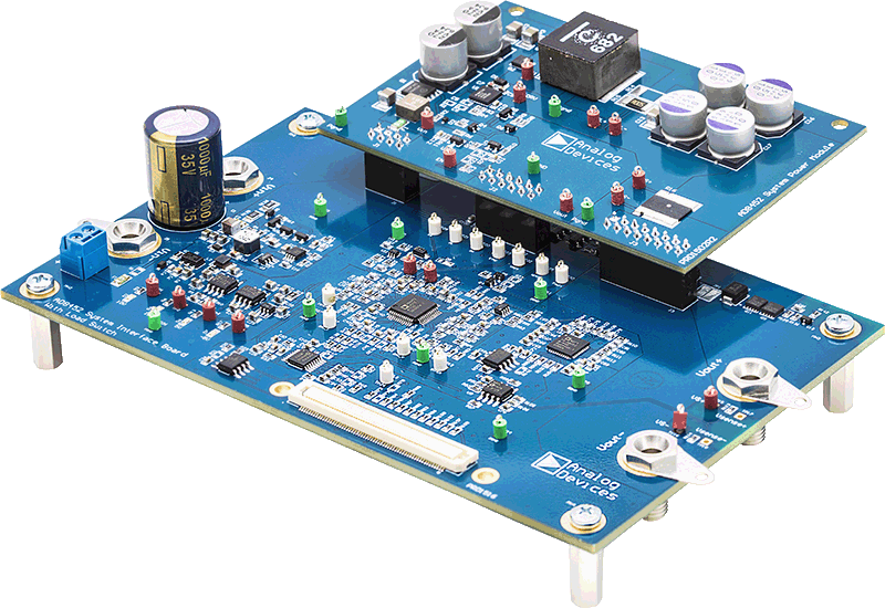
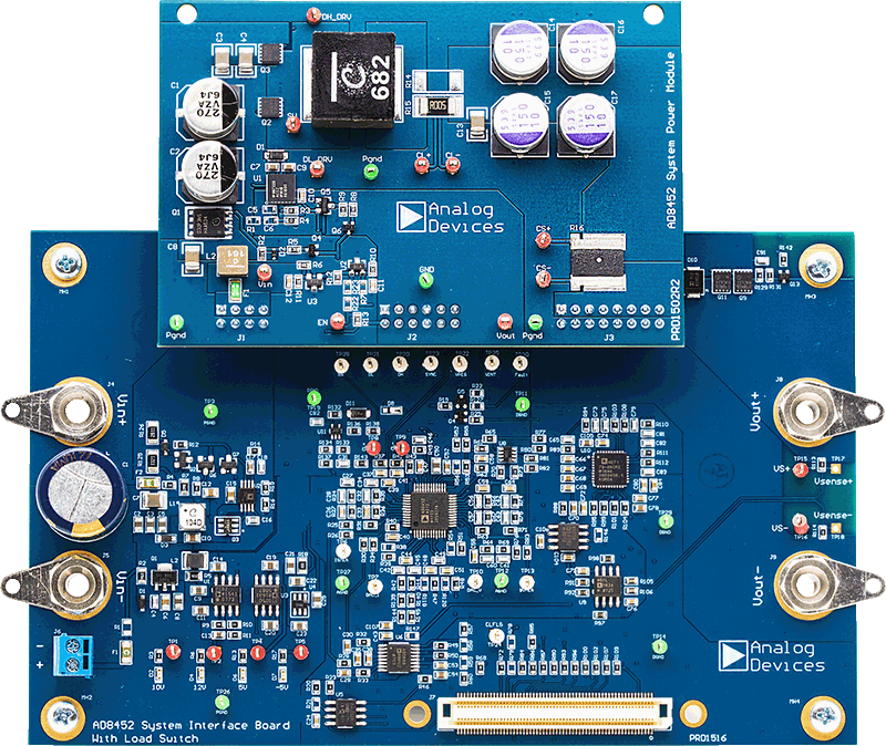
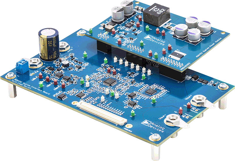
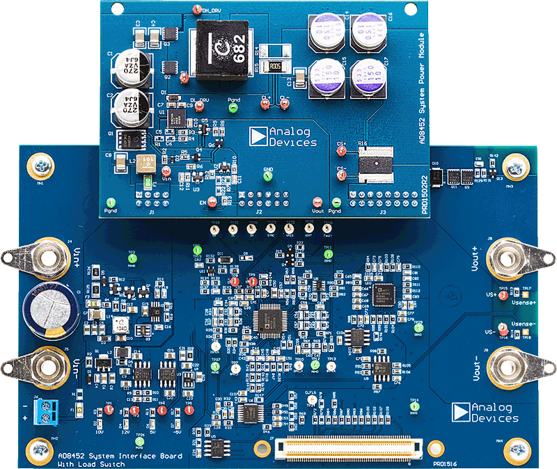
The AD8452 system demo evaluation kit is a recommended starting point for users building battery formation and test equipment based on the Analog Devices, Inc., AD8452 precision analog front end and pulse-width modulation (PWM) controller. The evaluation kit includes an analog interface board and a power module board.
In addition to the AD8452, the analog interface board also includes an AD5689R 16-bit, precision digital-to-analog converter (DAC) to set the current and voltage set points, and an AD7173-8 24-bit, Σ-Δ analog-to-digital converter (ADC) to monitor the battery voltage and current.
The analog interface board includes built-in voltage regulators so that it can be powered either from the bus power inputs or directly from a 15 V dc supply through a screw terminal connector.
The analog interface board connects to the Analog Devices System Demonstration Platform (SDP-S) through a 120-pin connector. The SDP-S board connects to the user interface software through the USB port, allowing the user to set the current and voltage set point as well as the mode of operation (charge or discharge). In addition, the user can monitor the battery voltage and current by reading the data output from the AD7173-8.
The analog interface board connects to the power module board through three multipin headers. This modular approach allows the user to design and test their own power module boards, designed for the current output range in their end applications, with the analog interface board of this reference design.
The standard power module board supports charge and discharge currents of up to 10 A. It includes the power metal-oxide semiconductor field effect transistors (MOSFETs), the inductor, and the input and output capacitors required to implement a buck or boost regulator, depending on the operating mode.
Full specifications of the AD8452 are available in the product data sheet, which must be consulted in conjunction with the user guide when working with the evaluation kit.
WARNING
When testing this system with lithium-ion (Li-Ion) batteries, take care not to overcharge or overdischarge the batteries, or to sink/source more than the maximum current recommended by the manufacturer of the battery. Exceeding these ratings can not only damage the battery, but can also cause it to explode or catch on fire.
Applicable Parts
Package Contents
- Analog interface board
- Power module board (10 V to 20 V dc operating range)
- SDP-S board for data transfer to PC
- Standard USB A to Mini-B USB cable
- Printed user guide
- Evaluation kit software CD
Getting Started
HARDWARE REQUIREMENTS
- Bench power supply, 12 V to 24 V dc (current depending on desired battery charge rate)
- Test battery or electronic load
- Windows PC with a USB port
Documentation & Resources
-
AD8452 System Demo Interface Board with Load Switch3/12/2021PDF2 M
-
UG-1181: AD8452 System Demo Evaluation Board (Rev. 0)11/2/2017PDF1 M