Overview
Product Details
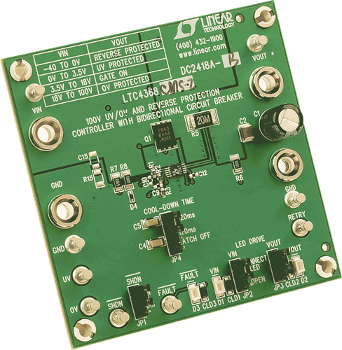
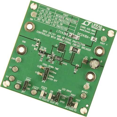
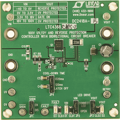
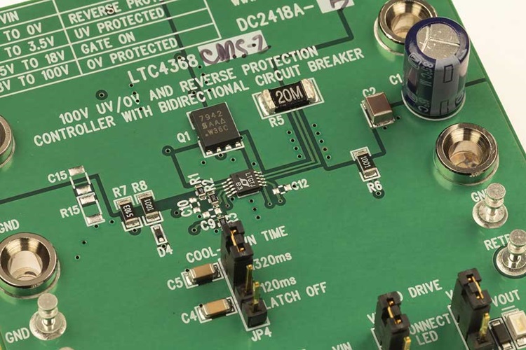
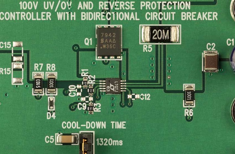
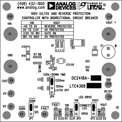
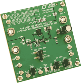
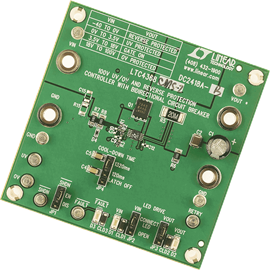
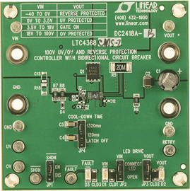
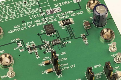
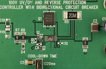
Demonstration circuit 2418A is intended to demonstrate the performance of the LTC4368 100V undervoltage (UV), overvoltage (OV), and reverse protection controller with bidirectional circuit breaker.
The LTC4368 protects circuits from overcurrent in both directions and from input voltages that may be too high, too low, or negative. The LTC4368 controls the gate voltage of two back-to-back connected external MOSFETs to ensure that the load is connected to the input supply only when there are no voltage or current faults. The OV and UV protection levels are adjusted by resistive dividers at the OV and UV pins, respectively. Asserting a low signal at the SHDN pin disables the MOSFETs and places the controller in a low-current shutdown state. The FAULT pin is asserted when the controller is in shutdown mode or when the input voltage is outside of the UV or OV window, or the load current exceeds the protection level, or the input voltage is below undervoltage lockout (1.8V to 2.4V).
After a forward overcurrent fault, the LTC4368 will either latch off power or retry after a user adjustable delay. A reverse overcurrent fault waits for the output to fall 100mV below the input to reconnect power to the load.
The LTC4368 can withstand DC voltages between −40V and 100V and has an operating range of 2.5V to 60V.
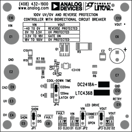
The DC2418A includes the LTC4368 controller, two backto- back connected power MOSFETs, current sense resistor, three jumpers, and three LEDs to indicate the input and output voltages and the FAULT pin signal.
Markets and Technologies
Applicable Parts
Documentation & Resources
-
Hot Swap Controllers8/2/2023PDF0 M
-
DC2418A - Schematic3/9/2017PDF37K
-
DC2418A - Demo Manual (Rev. A)3/9/2017PDF308 K
-
DC2418A - Design Files3/9/2017ZIP0M
