Regulated Dual Voltages Control STN-LCD Contrast
Abstract
This design note shows how a single IC generates the dual voltages required to control contrast in an STN LCD. The stable, dual-voltage LCD-contrast supply uses a dual-output boost converter, the MAX1677, and only four Schottky diodes and two flying capacitors.
A similar version of this article appeared in the May 21, 2001 issue of Electronic Design magazine.
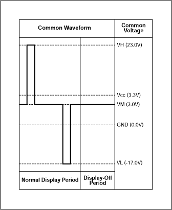
Generating a stable, dual-voltage, LCD-contrast supply can be difficult, especially if the two voltage amplitudes must track each other with respect to a given reference level. In Figure 1, the ±20V outputs are centered around a reference level (VM) of 3V. The contrast voltages must be symmetric about VM to avoid a DC component across the liquid crystal, which in turn would damage the LCD or shorten its life.

Figure 1. To avoid a damaging DC component across the LCD, these contrast waveforms are symmetric about the reference level VM.
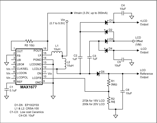
To create a triple-output regulated LCD supply, which produces a main-supply voltage and two LCD voltages symmetric around the LCD offset voltage (VM), we add four Schottky diodes (D1–D4) and two flying capacitors (C2–C3) to a dual-VOUT circuit (Figure 2). U1 normally supplies a digital VMAIN (typically 3.3V) and an LCD supply up to 28V. In Figure 2, the ±LCD output equals VM ± (LCD Reference output).

Figure 2. This single-IC circuit generates the dual voltages required to control contrast in an STN LCD.
U1 is a high-efficiency, dual-output boost converter for portable devices needing two regulated outputs. Operation with inputs as low as 0.7V allows it to accept 1-, 2-, or 3-cell alkaline, NiCd, or NiMH batteries, as well as 1-cell Li+ batteries. It requires no external switching FETs and draws only 20µA of supply current, making it ideal for handheld PDA and pen-input devices.
A switching FET internal to U1 repeatedly connects LCDLX (pin 12) to ground and then releases it, causing the LCDLX voltage to toggle between ground and LCDR plus one diode drop (LCDR is the LCD reference output). This action (similar to that producing the VMAIN output at pin 16) generates the ±LCD voltages as follows:
−LCD Output, Phase 1
The rise of LCDLX voltage to LCDR + VDIODE forces voltage on the other side of C3 to VM + VDIODE, creating a differential of LCDR − VM across C3. The LCDLX voltage is our reference point.
−LCD Output, Phase 2
As LCDLX goes to ground, the load side (-LCD Out) sees −LCDR + VM, forcing current from the −LCD load through D4. When this current flow discharges C3 slightly, the cycle starts again. Note that the +LCD and −LCD outputs develop on alternate phases. The resulting −LCD voltage is:
−LCD Out = −LCDR + VM + VDIODE
+LCD Side, Phase 2
When LCDLX goes to ground, the load side of C2 sees VM - VDIODE. Then, (phase 1) the rise of LCDLX to LCDR + VDIODE forces a voltage of LCDR + VM on the other side of C2. The +LCD load also sees an additional diode drop across D5:
+LCD Out = LCDR + VM − VDIODE
These load equations show that −LCD Out and +LCD Out track each other with respect to LCDR, and are offset by VM less one diode drop. The Schottky diodes D1-D5 can be MBR0530 or EP10QY03 types. C2-C3 can be 1µF, preferably with voltage ratings of at least 2LCDR. Typical L1–L2 values are 10µH each, and the output capacitors (C4–C6, shown as 10µF) may be sized according to the allowable output ripple.