Design Note 184: Micropower MSOP 10-Bit ADC Samples at 500ksps
Introduction
The LTC1197/LTC1199 10-bit serial ADCs offer small size, low power operation and fast sample rates with good AC and DC performance. These parts are ideal for low power, high speed and/or compact designs. This Design Note discusses the features and performance that make the LTC1197/LTC1199 excellent choices for such new designs.
Features
Smallest Size (MSOP)
The LTC1197/LTC1199 are among the smallest ADCs available. The LTC1197/LTC1199’s serial interface allows the use of 8-pin MSOP and SO packages. Although the SO package consumes little area, the MSOP package reduces the small footprint even further. These are some of the first ADCs available in the MSOP package, which is about half the size of the SO-8.
3V or 5V Supplies
The LTC1197/LTC1199 are 5V parts (VCC = 4V to 9V for the LTC1197 and 4V to 6V for the LTC1199). Also available for use in 3V systems are the LTC1197L and the LTC1199L (VCC = 2.7V to 4V). Designed for use in mixed-supply systems, these devices operate flawlessly even when the the digital input is greater than the VCC voltage. This is useful in systems where the ADC is running at a lower supply voltage than the processor. If the ADC is running at a higher supply voltage than the processor, the ADC serial data output voltage can easily be decreased to a level appropriate for the processor.
Performance
Micropower Performance with Auto Shutdown at Full Speed
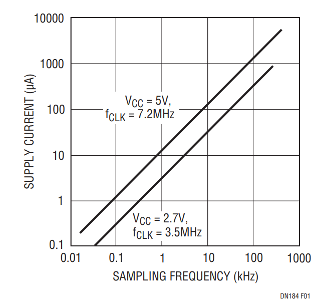
Running continuously, the LTC1197L consumes only 2.2mW at the maximum sampling rate (25mW for the LTC1197). The power consumption drops dramatically, as shown in Figure 1, at lower sampling rates. The formula for calculating power consumption is:
PD = VCC • ICC • tCONV • fS
where PD is the power consumption, VCC is the supply voltage, ICC is the supply current while the conversion is occurring, tCONV is the conversion time and fS is the sample rate. As you can see from the formula, lowering fS reduces the power consumption linearly. It is also important to minimize tCONV by clocking the ADC at its maximum rate during the conversion. In this way, the total power is less because the device is on for a shorter period of time.

Figure 1. The LTC1197/LTC1199 Reduce Their Supply Current Consumption and Save Power When Operating at Lower Sample Rates.
High Speed Capability
Even though the LTC1197/LTC1199 are capable of micropower operation, they are able to sample at rates of up to 500kHz. These parts can also digitize fast input signals up to the Nyquist frequency (250kHz for the LTC1197) with over nine effective number of bits (ENOBs).
Good DC and AC Specs
The DC specifications of these parts are very good. Linearity (both INL and DNL) is typically 0.3LSB with a maximum spec of 1LSB. Offset is specified at 2LSBs (max) and gain error is specified at 4LSBs (max). These specifications are guaranteed over the full temperature range of the part. Both commercial and industrial temperature range versions are available.
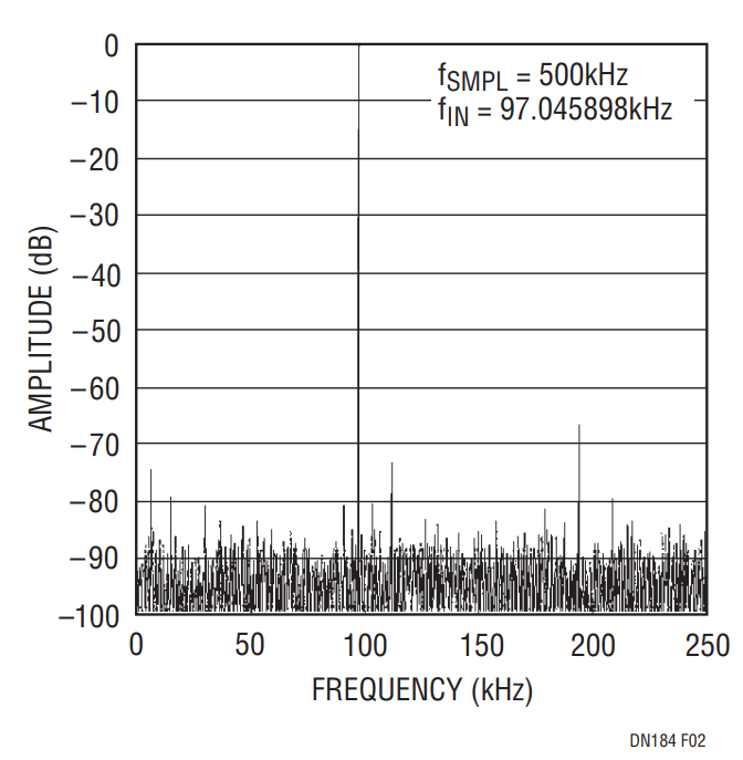
AC performance is equally impressive. S/(N + D) is typically 60dB (58dB for the L version). THD is typically –64dB (–60dB for the L version) and the peak harmonic or spurious noise is typically –68dB (–63dB for the L version). An FFT of the LTC1197’s conversion performance is shown in Figure 2.

Figure 2. The LTC1197’s Typical 60dB SINAD Shown in the FFT Curve is Among the Best and Translates into 9.7 Effective Bits.
Flexible Inputs
The LTC1197 has a single differential input and a wide range reference input. The reference input allows the full scale to be reduced to as low as 200mV. This translates to an LSB size of only 200μV. Combined with the high impedance of the analog input, this allows direct digitization of low level transducer outputs, which can save board space and the cost of a gain stage.
With its software-selectable 2-channel MUX, the LTC1199 is capable of measuring either one differential or two single-ended input signals. Both parts have a built-in sample-and-hold.
Serial I/O
The LTC1197/LTC1199 are hardware and software compatible with SPI and MICROWIRE protocols using either 3- or 4-wire serial interfaces. This compatibility is achieved with no additional circuitry, allowing easy interface to many popular processors.
Battery Current Monitor
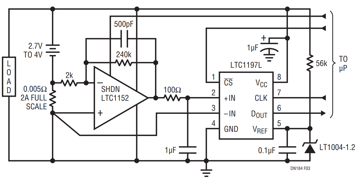
Figure 3 shows a 2.7V to 4V battery current monitor that draws only 45μA from the battery it monitors. Supply current is conserved by sampling at 1Hz and using the LTC1152’s shutdown pin to keep the op amp off between conversions. The LTC1197 automatically shuts down after a conversion. The circuit can be located near the battery, serially transmitting data to the microprocessor.

Figure 3. This 0A to 2A Battery Current Monitor Draws Only 45μA from a 3V Battery.
Conclusion
Conserving space and power, the LTC1197/LTC1199 have a small footprint and are capable of micropower operation. They have a versatile, SPI/MICROWIRE compatible serial interface. The adjustable reference input, 2-channel, software-selectable MUX and 5V or 3V operation increase this ADC family’s versatility. When this versatility is combined with the high conversion rate and good DC and AC performance, you can see why these ADCs are good choices for low power, high speed and/or compact designs.
