Design Note 167: The LTC1590: Applications Versatility of Dual 12-Bit DAC
Introduction
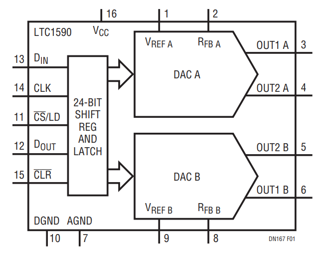
CMOS multiplying digital-to-analog converters (MDACs) make versatile building blocks that go beyond their basic function of converting digital data into analog signals. This Design Note details some of the other circuits that are possible when using the LTC1590 dual, serial 12-bit current output DAC. This DAC, shown in Figure 1, features:
- 2- and 4-Quadrant Multiplying Capability
- Outstanding INL and DNL: 0.1LSB Typ, 0.5LSB Max Over Temperature
- Low Supply Current: 10μA
- 3-Wire, Daisy-Chainable SPI Serial I/O
- Clear Input Resets DACs to Zero Scale
- Small Footprint: Narrow 16-Lead SO Package
The LTC1590 is designed for a wide range of applications, including process control and industrial automation, automatic test equipment, software-controlled gain adjustment, digitally controlled filters and power supplies. This DAC is available in 16-lead narrow SO and PDIP packages.

Applications
Digitally Controlled Attenuator and PGA
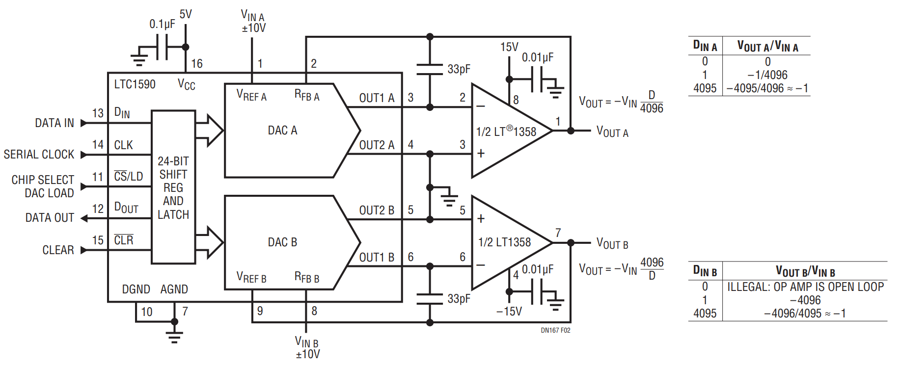
The circuit shown in Figure 2 uses the LTC1590 to create a digitally controlled attenuator using DAC A, and a programmable gain amplifier (PGA) using DAC B. The attenuator's gain is set using the following equation:
Where:
VOUT = output voltage
VIN = input voltage
n = DAC resolution in bits
D = value of code applied to DAC
The attenuator’s gain varies from 0 to –4095/4096 in 4096 steps. A code of 0 completely attenuates the input signal.
The PGA’s gain is set using the following equation:
Where:
VOUT = output voltage
VIN = input voltage
n = DAC resolution in bits
D = value of code applied to DAC
The gain is adjustable from –4096/4095 to 4096 in 4095 steps. A code of 0 is meaningless, since this results in infinite gain and the amplifier operates open loop. With either configuration, the attenuator's and PGA's gains are set with 12-bit accuracy.
Amplified Attenuator and Attenuated PGA
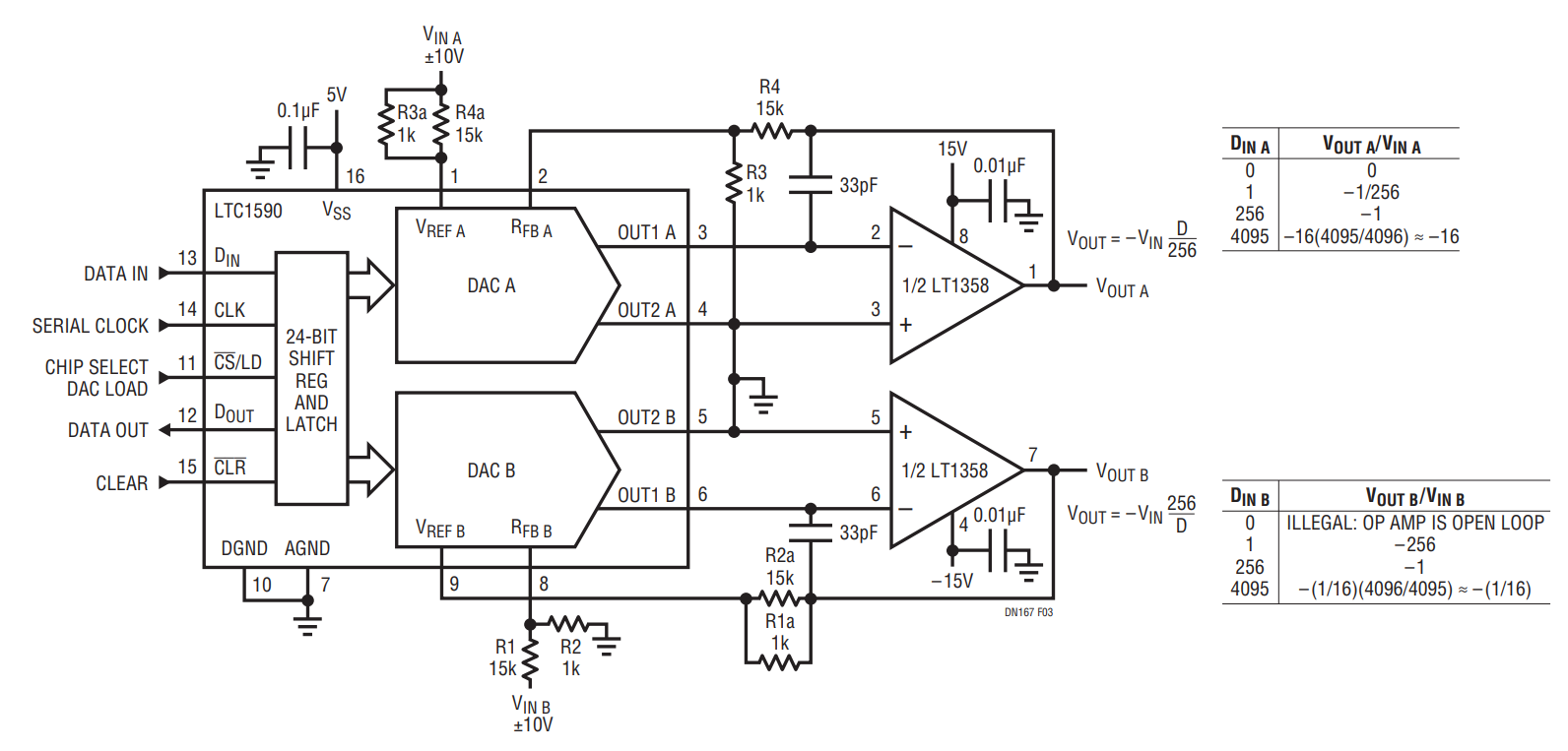
Further modification to the basic attenuator and PGA is shown in Figure 3. In this circuit, DAC A’s attenuator circuit is modified to give the output amplifier a gain set by the ratio of resistors R3 and R4. The equation for this attenuator with output gain is:
With the values shown, the attenuator’s gain has a range of 0 to approximately –16. This range is easily modified by changing the ratio of R3 and R4. In the other half of the circuit, an attenuator has been added to the input of DAC B, configured as a PGA. The equation for this PGA with input attenuation is:
This sets the gain range from approximately –1/16 to –256. Again, a code of 0 is meaningless. This range can be modified by changing the ratio of R1 and R2.


