Resource Library
Design Note 225: Low Cost, High Efficiency 42A DC/DC Converter
Introduction
The LTC1709-8/LTC1709-9 are dual, current mode, 2-phase controllers that drive two synchronous buck stages out of phase. This architecture reduces the number of input and output capacitors without increasing the switching frequency. The relatively low switching frequency and integrated high current MOSFET drivers help obtain high power conversion efficiency for low voltage, high current applications. Because of the output ripple current cancellation, lower inductance values can be used, resulting in faster load transient response. This, plus a 5-bit VID programmable attenuator, makes it particularly attractive for CPU power supply applications. Two VID tables are available to comply with VRM8.4 (LTC1709-8) and VRM9.0 (LTC1709-9).
Design Example
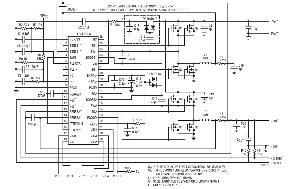
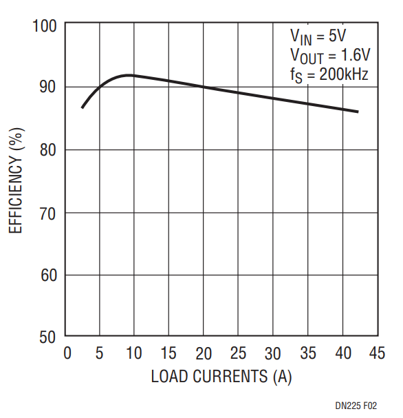
Figure 1 shows the schematic diagram of a 42A power supply for the AMD Athlon microprocessor. With only one IC, eight tiny SO-8 MOSFETs and two 1μH low profile surface mount inductors, an efficiency of 86% is achieved for a 5V input and a 1.6V/42A output. Greater than 85% efficiency is maintained throughout the load range between 3A and 42A as shown in Figure 2

Figure 1. Schematic Diagram of a 42A AMD Athlon Microprocessor Power Supply Using the LTC1709.

Figure 2. Efficiency vs Load Currents
Because of the low input voltage, the reverse recovery losses in the body diodes of the bottom MOSFETs are not significant. No Schottky diodes are required in parallel with the bottom MOSFETs in this application.
Table 1 compares the input and output ripple currents for single phase and 2-phase configurations. A 2-phase converter reduces the input ripple current by 50% and the output ripple current by 75% compared to a single-phase design. The resulting savings in input and output capacitors is significant
| Phases | Input Ripple Current (ARMS) | Output Ripple Current (AP-P) |
| 1 | 19.7 | 10.9 * |
| 2 | 10.1 | 2.9 |
| * Assumes that the single phase circuit uses two 1μH/21A inductors in parallel to provide 42A output. | ||
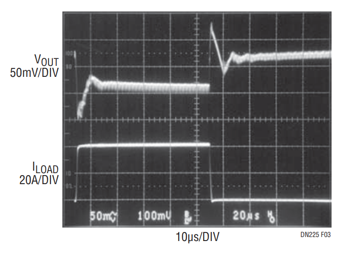
Figure 3 shows the measured load transient waveform. The load current changes between 2A and 42A with a slew rate of about 30A/μs. Output capacitor requirements are dominated by the total ESR of the output capacitor network. Six low-cost Aluminum electrolytic capacitors (Rubycon, 1500μF/6.3V) are needed on the output to meet this requirement. The maximum output voltage variation during the load transients is less than 200mVP-P. Active voltage positioning was employed in this design to reduce the number of output capacitors (refer to Design Solutions 10 for more details on active voltage positioning). R4 and R6 provide the desired load regulation with no efficiency loss. If OS-CON capacitors are used, four 1200μF/2.5V (2R51200M) capacitors will be sufficient.

Figure 3. Load Transient Waveforms at 40A Step and 30A/μs Slew Rate.
Conclusion
The LTC1709-based, low voltage, high current power supply achieves high efficiency and small size simultaneously. The savings in the input and output capacitors, inductors and heat sinks help minimize the cost of the overall power supply. This LTC1709 circuit, with a few minor modifications, is also suitable for Intel VRM9.0 applications. Refer to Application Note 77 for more information on the PolyPhase® technique
