AN-2639: An Overview on Congestion Management in Ethernet and Deterministic Networks

AN-2639: An Overview on Congestion Management in Ethernet and Deterministic Networks
Introduction
This application note provides an overview of congestion in Ethernet networks, including both standard best effort and deterministic time-sensitive networking (TSN) systems, and outlines techniques to mitigate its impact. Network congestion occurs when the volume of data traffic exceeds the available capacity of one or more Ethernet links. This results in increased latency due to queuing delays, packet loss when buffers are exhausted, and reduced overall network efficiency as effective throughput decreases.
Designing a network that minimizes congestion requires careful system level planning, appropriate traffic engineering, and ongoing performance monitoring. While it is not always possible to completely eliminate congestion, particularly in bursty or high demand scenarios, well-established techniques such as traffic prioritization, shaping, scheduling, and rate limiting enable networks to operate efficiently while maintaining predictable and reliable performance.
The ADIN3310/ADIN6310 switches support key TSN features, including time aware scheduling (IEEE 802.1Qbv), frame preemption (IEEE 802.1Qbu / IEEE 802.3br), and per stream filtering and policing (IEEE 802.1Qci). These capabilities enable the implementation of deterministic Ethernet systems with bounded latency, low jitter, and controlled traffic behavior.
While the switch provides hardware support for these TSN mechanisms, achieving deterministic end-to-end system performance requires coordinated configuration across all traffic sources and network nodes. In particular, traffic schedules, bandwidth allocation, and traffic contracts must be carefully engineered at the system level to fully realize the benefits of TSN and ensure predictable operation under all traffic conditions.
Topologies
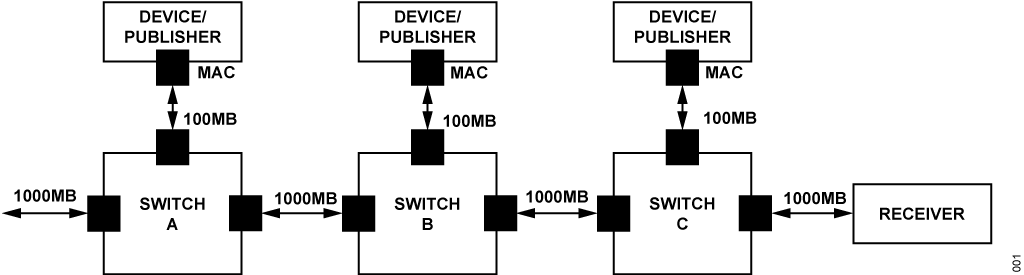
Line Topology
In a line topology, devices are connected in a single sequential chain, with each device connected to two neighboring devices. Traffic is typically directed toward a receiving device at one end of the line. This type of application can be implemented using a 3-port switch, where two ports face the network and the third connects to the MAC interface of the device publishing data. In the line topology as shown in Figure 1, traffic originating from the device on the left enters the network at Switch A and must traverse each intermediate switch to reach the receiving node on the right. If the device connected to switch A transmits large volumes of data, the downstream switches (Switch B and Switch C) experience the same traffic load. When multiple end devices are connected at a 1000Mbps line rate and inject traffic simultaneously, congestion can occur within the switches. This may lead to packet loss due to buffer overflow or increased latency caused by excessive queuing delays.
Tree Topology
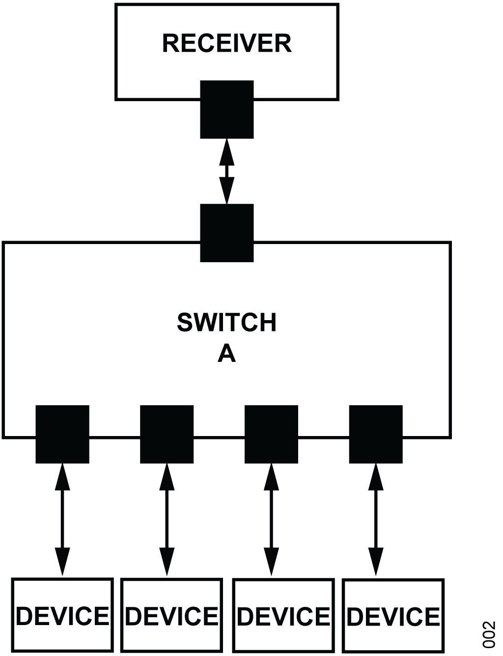
A tree topology follows a hierarchical structure, with an upstream switch connecting multiple layers of downstream devices. Traffic generated by lower tier nodes is aggregated as it moves upward through the hierarchy toward the receiving devices. While this topology scales well and simplifies network expansion, congestion can occur at aggregation points if the combined traffic exceeds the available uplink capacity. Without adequate bandwidth provisioning, traffic shaping, or prioritization, these bottlenecks can lead to increased latency and packet loss.
Congestion Management
To manage congestion, a range of techniques can be employed, including flow control, traffic shaping, load balancing, and quality of service (QoS). These mechanisms are used to regulate traffic rates, prioritize critical data flows and ensure efficient use of available network bandwidth.
For non-deterministic traffic, congestion management is often implemented at the traffic source through bandwidth allocation mechanisms. For example, a device may be configured with a maximum allowable transmit bandwidth per traffic flows/classes. These limits are managed to ensure that the aggregate bandwidth generated by all producers can be sustained by the network without overwhelming intermediate switches. Additional congestion management techniques are also available at higher layers of the open systems interconnection (OSI) model.
When intermittent or non-deterministic traffic is predominantly transmission control protocol (TCP) based, TCP window sizes can be tuned at the traffic sources to limit the amount of data in flight. This helps prevent switch buffers from being overrun as traffic traverses the network. Similar rate limiting and flow regulation mechanisms are available for many bulk data transfer protocols operating over user datagram protocol (UDP).
Flow Control
In systems that do not have strict determinism and low latency requirements, Ethernet flow control mechanisms such as IEEE 802.3x, can be used to manage congestion. This approach is most effective when all switches in the network, as well as high volume traffic producing nodes, support and correctly implement the protocol.
IEEE 802.3x flow control operates by monitoring switch buffer utilization. When buffer resources approach a critical threshold, the switch transmits pause frames to connected devices, temporarily halting incoming traffic. This pause allows buffered frames to be forwarded downstream and prevents intermediate packet loss. In practice, pause frames may propagate upstream through multiple switches until they reach the traffic producers, causing transmission to be suspended for a short period. While effective for preventing packet loss in best effort or bulk transfer applications, Ethernet flow control is generally unsuitable for high performance systems with strict determinism or latency requirements. The use of pause frames can lead to unpredictable delays and priority inversion, which conflicts with the requirements of deterministic Ethernet networks.
Note that IEEE 802.3x flow control is not supported by ADIN3310/ ADIN6310.
Congestion Management in Real-Time Use Cases Such as TSN (Time Sensitive Networking)
The IEC 60802 TSN profile for industrial automation explicitly requires that IEEE 802.3x Ethernet flow control be disabled. In real-time communication systems, such as those used in industrial automation, traffic behavior must be tightly controlled to meet strict latency, jitter and delivery guarantees. Critical time sensitive streams are carefully planned and assigned to high priority traffic classes with reserved resources.
For applications requiring tighter timing guarantees and assured bandwidth, mechanisms such as traffic scheduling, frame pre-emption, and other TSN techniques are employed to control when and how traffic enters the network. Traffic that does not require strict determinism is assigned to lower priority classes, where shaping techniques such as the credit based shaper (CBS) can be used to provide some fairness among classes while preventing interference with critical streams. To ensure that no network link becomes oversubscribed, resulting in frame loss or excessive latency, the worst-case traffic load must be constrained at the traffic sources. In TSN systems, this is achieved by engineering and enforcing traffic contracts at the producers. For critical real time streams, these traffic characteristics are known in advance and can be precisely controlled.
Source Scheduling
Source scheduling uses time synchronization to coordinate traffic transmission from publishers so that bursts do not overlap and contend for network resources. Scheduling traffic at the publisher ensures that frames are injected into the network at predefined times, reducing the need for large buffering resources within switches. Some switches may assist the publishers transmitting data by providing timing signals or hardware triggers, enforcing scheduling at the source is essential for maintaining deterministic behavior. The ADIN3310/ADIN6310 provide four hardware timer output pins that can be configured to execute user-defined schedules. These timers enable precise synchronization of host actions by generating trigger events at predetermined times, allowing the host processor to initiate operations such as sensor measurements, data acquisition, or Ethernet frame transmission.
Source Rate Limiting
Source rate limiting ensures that a publisher cannot transmit bursts at line rate. By constraining the maximum transmission rate, traffic can be shared more predictably across the network, preventing transient congestion and protecting lower capacity links from overload.
Limiting Host Interface
In certain topologies, such as line topologies, reducing the publishers host interface speed can effectively limit the maximum amount of traffic injected into the network. This approach provides a simple and deterministic means of preventing downstream congestion by matching traffic generation rates to available network capacity.
Traffic Shaping and Policing
Traffic shaping techniques, such as leaky bucket and token bucket algorithms, regulate traffic by smoothing bursts and enforcing sustained data rates that the network can accommodate. These mechanisms improve predictability and help prevent congestion by controlling how traffic is released into the network.
Traffic policing complements shaping by enforcing strict rate limits and discarding frames that exceed defined thresholds. Policing is often combined with quality of service (QoS) mechanisms to ensure that critical traffic is protected, while less critical traffic is constrained or dropped when necessary.
| Aspect | Standard Ethernet Networks | TSN/Real-Time Ethernet Networks |
| Primary goal | Maximize throughput and fairness | Guarantee bounded latency and deterministic delivery |
| Congestion handling approach | Reactive and adaptive | Proactive and engineered |
| Traffic characteristics | Bursty, unpredictable | Known, planned, and bounded |
| Flow control | IEEE 802.3x Ethernet Flow Control | Disabled per IEC 60802 TSN Profile |
| Congestion location | Managed within switches and end systems | Prevented at traffic sources by engineering traffic |
| Traffic prioritization | QoS using IEEE 802.1Q PCP | Strict priority and reservation using IEEE 802.1Q |
| Traffic shaping | Optional, best effort shaping | Credit based Shaper (IEEE 802.1Qav) for non-critical traffic |
| Scheduling | No time awareness | Time aware Shaper (IEEE 802.1Qbv) |
| Frame preemption | Not typically used | Frame Preemption (IEEE 802.1Qbu/IEEE 802.3br) |
| Rate limiting | Dynamic or adaptive | Engineered worst-case limits at the source (IEEE 802.1Qci) |
| Packet loss | Generally acceptable | Not acceptable for critical streams |
| Latency and jitter | Variable and load dependent | Bounded and tightly controlled |
Switch Considerations, Buffering
Frame Buffering
Switches use frame buffers to temporarily store frames when the egress port is busy. Depending on the switch architecture, these buffers may be shared across multiple ports (centralized buffering) or dedicated per port. While shared buffering can improve memory efficiency under uneven traffic conditions, it introduces interport contention that may increase latency variability. Per port buffering isolates traffic classes and congestion domains, enabling bounded latency and predictable behavior, making it the preferred approach for deterministic and time-sensitive networking applications. In both cases, the buffer size is finite, limiting the number of frames that can be stored. If multiple frames arrive simultaneously targeting the same egress port, the buffer can fill, resulting in congestion and potential frame loss. Proper network design, traffic shaping and rate limiting are essential to prevent buffer overflow, particularly in high throughput or real-time applications.
The size of a switches frame buffers directly impacts its ability to handle traffic bursts without dropping frames. When architecting buffer sizing, consideration is given to link speed, maximum frame size, expected burst traffic and network topology. In TSN, traffic is scheduled and shaped at the source, so buffers are primarily used to absorb residual bursts and to handle lower priority or best effort traffic.
ADIN3310/ADIN6310 Buffering
The Analog Devices, Inc. switch supports a dedicated 32kB buffer for each transmit port, implemented as 220 buffer segments of 144 bytes each, with effectively 202 buffer segments made available. The switch supports eight priority queues per port and employs strict priority traffic scheduling. Under strict priority, frames are classified into queues based on priority, and the switch always services the highest priority non-empty queue first. Frames in lower priority queues are only transmitted when all higher priority queues are empty. The per port buffer is shared across all the queues. Each queue can support up to 32 frames, however if the ports frame buffer becomes exhausted, the switch resolves congestion by dropping the oldest frames from the lowest priority queue.
The number of buffer segments consumed depends on the frame size. A centralized buffer manager tracks buffer availability and ensures that buffers segments are released once frames have been transmitted or discarded. In segment terms, the buffer can hold roughly 18 to 19 standard maximum transmission unit (MTU) sized (1500 byte) frames. While jumbo frames can be sent across the switch, they consume buffer capacity quickly reducing headroom for smaller, latency sensitive frames. Avoid jumbo frames in TSN/ industrial traffic on ADIN6310 unless isolated to best-effort queues. In most industrial TSN use cases, frame sizes are typically much smaller, making the switches buffer size well suited to these use cases.
| Frame Size | Segments Needed | Frames per Buffer |
| 64B | 1 segment | 202 |
| 256B | 2 segments | 101 |
| 512B | 4 segments | 50 |
| 1500B | 11 segments | 18-19 |
| 9k jumbo | ~63 segments | ~3 frames |
The per port buffer architecture of the switch is well aligned with optimization for deterministic TSN operation, prioritizing predictability and low latency. At 10Mbps and 100Mbps, the buffer provides generous millisecond scale timing margin, comfortably absorbing timing variations, serialization effects, and minor schedule variations. Even at 1Gbps it provides a clearly defined and manageable buffering window that must be incorporated into TSN latency budgets and traffic schedules. See Table 3.
| Port speed | Approximate Buffer time |
| 10Mbps | ~23.3ms |
| 100Mbps | ~2.33ms |
| 1000Mbps (1Gbps) | ~233µs |
Design Guidelines for Congestion Management With ADIN3310/ADIN6310
Effective congestion management in an ADIN6310 based network starts with correct traffic engineering at the system level. The switch provides per-port buffering, eight transmit priority queues per port, strict priority scheduling, and congestion visibility through extended statistics and buffer utilization notifications. However, deterministic operation is achieved primarily by preventing sustained over-subscription of any egress port and by ensuring that high priority traffic is bounded at the source.
The calculation must include all traffic classes that may be active at the same time, including cyclic control traffic, event-driven traffic, diagnostics, protocol overhead, and background best effort traffic. Engineering margin must be included to account for burstiness, frame overhead, clock tolerance, and unexpected traffic patterns.
For deterministic applications, the worst-case traffic pattern must be bounded. The network must not rely on switch buffering as the primary congestion control mechanism. Buffers must be considered a short-term absorption mechanism for residual bursts, timing variation, and lower priority traffic, rather than a substitute for correct bandwidth planning. In TSN enabled systems, congestion is prevented through a combination of source traffic control and switch level mechanisms such as time aware scheduling and per stream traffic enforcement.
Traffic Classification and Priority Assignment
Network traffic must first be classified according to timing criticality, loss tolerance, and bandwidth requirements. Time-sensitive control, synchronization, and protection traffic should be assigned to higher priority queues, while engineering, diagnostic, firmware update, and best effort traffic should be assigned to lower priority queues.
In virtual local area network (VLAN) tagged networks, IEEE 802.1Q priority code point (PCP) values can be used to classify traffic into the available transmit queues. The priority mapping must be configured so that critical traffic is placed in higher priority queues and noncritical traffic is placed in lower priority queues. The ADIN6310 supports eight priority queues per port and uses strict priority scheduling, where the highest priority non-empty queue is serviced first. By default, the switch routes all untagged frames to Queue 0, and the VLAN traffic classes are mapped 1:1 to the other queues, this must be reconfigured as required by use case. PTP and LLDP frames are routed to Queue 7 by default and must be programmed to egress from a different queue.
When using strict priority scheduling, the bandwidth of high priority traffic must be constrained. If high priority traffic is allowed to consume the full egress bandwidth for an extended period, lower priority queues may experience excessive latency or starvation. For this reason, high priority traffic must be rate limited, shaped, or scheduled at the source.
Avoid Sustained Egress Oversubscription
Congestion occurs when the aggregate ingress traffic targeting a given egress port exceeds the egress port capacity. This condition is especially important in line and tree topologies, where traffic from multiple producers can converge on a single downstream link or aggregation point.
For each egress link, the following condition must be verified during network design:
sum of worst-case ingress traffic rates to an egress port < available egress link rateControl Traffic at the Source
In deterministic and time-sensitive systems, congestion must be prevented before traffic enters the network. Source-based control mechanisms include scheduling, rate limiting, host interface limiting, and traffic shaping.
Source scheduling is preferred when traffic is cyclic and predictable. Publishers must transmit frames at defined times so that bursts from multiple devices do not overlap at shared egress points. This reduces queue buildup within intermediate switches and improves latency predictability.
Source rate limiting must be used when a producer can generate traffic faster than the network can forward it. This approach is particularly important for diagnostic, logging, firmware update, or bulk transfer traffic that may otherwise transmit at line rate.
In some line topology applications, limiting the host interface speed of the producer can provide a simple and deterministic upper bound on injected traffic. For example, reducing the host side interface rate can prevent a local processor from injecting sustained 1Gbps traffic into a path that must also carry traffic from other devices.
Reserve Bandwidth for Critical Traffic
Critical traffic must be assigned sufficient bandwidth and priority to meet its latency and loss requirements. However, priority alone does not guarantee deterministic behavior. The aggregate rate of all high priority streams must remain below the available egress capacity.
A practical design approach reserves only the bandwidth required for critical traffic and leaves the remaining capacity for lower priority traffic. Best effort traffic must be constrained so that it cannot interfere with scheduled or high priority traffic. Where possible, best effort traffic must be shaped at the source and assigned to lower priority queues.
For industrial applications, small cyclic frames are typically more suitable for deterministic operation than large burst transfers. Large frames increase serialization time and consume more buffer resources. Jumbo frames must generally be avoided on links carrying time-sensitive traffic unless they are isolated to lower priority traffic classes and the impact on latency has been fully analyzed. The ADIN6310 buffer description shows that larger frames consume substantially more buffer segments, reducing the available headroom for other traffic.
Use Buffer Capacity as Design Margin, Not as Sustained Storage
The ADIN6310 provides a dedicated transmit buffer per port. The buffer is shared across the eight transmit queues associated with that port. The number of buffer segments consumed depends on frame size, with approximately 18 to 19 standard 1500 byte Ethernet frames fitting in the available buffer space, while jumbo frames consume buffer capacity much more quickly.
The buffering time available depends on the port speed. At lower link speeds, the same buffer depth provides a longer time margin; whereas at 1Gbps, the buffer provides a shorter but well-defined buffering window. This makes buffer analysis important when designing cascaded or aggregated topologies. A useful first order estimate for buffer absorption time is:
Buffer absorption time = available buffer bytes / egress line rate in bytes per secondThis estimate serves as a guideline only. Actual behavior depends on frame size, queue priority, ingress timing, egress utilization, and whether higher priority queues are continuously active.
Validate Worst Case Traffic Patterns
Network validation is performed using the worst-case expected traffic profile rather than average traffic. The validation profile includes simultaneous transmission from multiple producers, maximum expected frame sizes, diagnostic or background traffic, and any event-driven bursts that may occur during system operation.
For line topologies, validation includes the case where multiple upstream devices transmit toward the same downstream receiver. For tree topologies, validation includes the aggregation point where traffic from several branches converges on a common uplink. These are the most likely points for congestion to occur.
The validation objective is to confirm that:
- Critical traffic is not dropped.
- Critical traffic latency remains within the application budget.
- Lower priority traffic does not consume excessive buffer resources.
- Queue drop counters remain at zero for protected traffic classes.
- Buffer utilization remains within the selected design margin.
- No egress link is persistently oversubscribed.
Monitor Buffer Utilization During Validation
The ADIN6310 provides extended statistics that can be used to detect congestion during system validation and field diagnostics. The SES_GetExtendedStatistics() API reports per queue drop counts, maximum buffer usage, current buffer usage, and buffer-related interrupt status. A nonzero queue drop count indicates that frames have been discarded from a transmit queue. The SES_ClearExtendedStatistics() API can be used to clear these statistics counts per port.
The buffer utilization notification mechanism can also be used to detect when transmit buffer usage exceeds a configured percentage threshold. The SES_SetBufferUsageNotification Limit() API configures the alert threshold, and the SES_txBufferUtilizationAlertEvent reports the port, configured limit, and actual buffer utilization when the event is triggered.
During validation, the following indicators should be monitored:
- queueDropCount[n] greater than zero Indicates that frames were dropped from transmit queue n.
- maxNumbOfBuffers approaching the port buffer limit Indicates that the port is experiencing high transient or sustained buffering demand.
- bufferLimitIrq asserted Indicates that the buffer limit is reached.
- bufferAllocateIrq asserted Indicates that a buffer cannot be allocated.
- Repeated buffer utilization alerts Indicates that the selected traffic pattern is operating close to the available buffering margin.
As a practical guideline, the buffer utilization alert threshold can be set below the maximum buffer limit during validation, for example, in the 70% to 80% range, to provide an early indication of insufficient traffic margin. The optimum threshold depends on the application latency budget, frame size distribution, and expected burst profile.
The following snippet from the SES_switch.h header file shows additional detail around the extended statistics and buffer insight.
/** @brief This data structure is used to pass the extended statistics for a port */
typedef struct {
uint32_t queueDropCount[8];
/**< Number of dropped packets for transmit queues 0 through 7 */
uint32_t maxNumbOfBuffers;
/**< Highest number of buffers used (0-219) */
uint32_t curNumbOfBuffers;
/**< Current number of buffers in use (0-219) */
/** Once an IRQ statistic is set, it remains set until actively cleared,
* indicating an interrupt occurred even if it has already been serviced. */
uint32_t bufferLimitIrq;
/**< Set to 1 if the buffer limit of 219 is reached */
uint32_t bufferParityErrorIrq;
/**< Set to 1 if a buffer parity error occurred */
uint32_t bufferAllocateIrq;
/**< Set to 1 if a buffer could not be allocated */
uint32_t bufferReturnErrorIrq;
/**< Set to 1 if a buffer could not be returned */
} SES_extendedStatistics_t;
Buffer Utilization
Additionally, the switch provides visibility into buffer utilization, and the host can request a notification when transmit buffer exceeds a set threshold. The percentage utilization is configured using the SES_SetBufferUsageNotificationLimit() API, and the host can subscribe to the notification, SES_txBufferUtilizationAlertEvent parameter, (see driver header SES_event.h). The following snippet from the SES_switch.h header file shows the information provided when such an event is flagged.
//** @brief This structure provides context for the TX Buffer Utilization
* Alert event generated by SES */
typedef struct {
uint32_t port;
/**< Port that generated the buffer utilization alert */
uint32_t utilizationAlertSetPercent;
/**< Buffer usage limit in percent to generate the event */
uint32_t utilizationAlertSetBuffers;
/**< Buffer usage limit in number of buffers to generate the event */
uint32_t utilizationAlertTriggeredPercent;
/**< Buffer usage in percent at which the event was triggered */
uint32_t utilizationAlertTriggeredBuffers;
/**< Buffer usage in number of buffers at which the event was triggered */
} SES_txBufferUtilizationAlertEventParam_t;
Aggregation Point Congestion in a Tree Topology
The following example illustrates how congestion can occur at an aggregation point even when individual traffic streams appear modest:
- System configuration:
- Three field devices connected to a downstream switch
- Each device generates cyclic data:
- Frame size: 256 bytes, transmission rate: 2000 frames per second
- All traffic is forwarded to a single upstream link
- Uplink speed: 10Mbps
- Per device traffic rate: 256 bytes × 2000 frames/s = 512,000 bytes/s ≈ 4.1Mbps
- Aggregate traffic load: 3 × 4.1Mbps = 12.3Mbps
- Analysis: 12.3Mbps >10Mbps → sustained oversubscription
- Resulting behavior:
- Frames accumulate in the switch transmit buffer, causing queue depth to increase and resulting in added latency. As buffer capacity becomes exhausted, frames are dropped, starting from the lowest priority queues. High-priority traffic may still be forwarded if bandwidth is reserved, while lower priority traffic experiences increased latency and potential starvation. If high-priority traffic is not bounded, all traffic classes may be affected.
- Average per device bandwidth appears low, but combined traffic exceeds link capacity
- Congestion occurs continuously (not just in bursts)
- Buffering cannot compensate for sustained oversubscription
Traffic Accumulation in a Line Topology
The following example illustrates how congestion can occur in a line topology as traffic accumulates along the path toward a receiving device, even on higher bandwidth links:
- System configuration:
- Four switches connected in a line topology
- Each switch has one locally connected field device
- All field devices transmit cyclic data toward a controller at one end of the line
- Each field device generates:
- Frame size: 512 bytes, transmission rate: 5000 frames per second
- Network link speed between switches: 100Mbps
- Per device traffic rate (each device contributes approx 20.5Mbps):
- 512 bytes × 5000 frames/s = 2,560,000 bytes/s
- 2,560,000 × 8 = 20.48Mbps
- Link from Switch D to Switch C: 1 device → 20.5Mbps
- Link from Switch C to Switch B: 2 devices → 41.0Mbps
- Link from Switch B to Switch A: 3 devices → 61.5Mbps
- Link from Switch A to Controller: 4 devices → 82.0Mbps
- Analysis: 82.0Mbps < 100Mbps → no sustained oversubscription (steady state safe)
- Worst-case burst condition: If all devices transmit simultaneously (aligned cycles) and additional noncritical traffic is present (for example, diagnostics or engineering traffic at 30Mbps): 82Mbps + 30Mbps ≈ 112Mbps > 100Mbps resulting in transient or sustained oversubscription if the condition persists.
Downstream links closest to the controller experience the highest load. Frames accumulate in transmit buffers of Switch A and Switch B. Increased queuing delay for all traffic. Under sustained overload, buffer exhaustion occurs and frames are dropped starting from lowest priority queues. Under strict priority scheduling, high-priority traffic continues to be forwarded, while lower-priority traffic may experience starvation.
Even when average utilization appears acceptable on a 100Mbps network, traffic accumulation in a line topology can create hotspots near the controller. Worst-case behavior must consider both simultaneous transmission and additional background traffic, as these conditions can drive transient or sustained congestion despite nominal link headroom.
Line Topology Example, 1gbps Network
The following example illustrates traffic accumulation in a line topology where multiple devices transmit toward a controller at one end of the network. Although a 1Gbps network provides significant bandwidth margin, worst-case traffic accumulation and burst alignment must still be considered.
- System configuration:
- Four switches connected in a line topology
- Each switch has one locally connected field device
- All field devices transmit cyclic data toward a controller at one end of the line
- Each field device generates cyclic process data:
- Frame size: 512 bytes
- Transmission rate: 10000 frames per second
- Network link speed between switches: 1Gbps
Per device traffic rate:
- 512 bytes × 10,000 frames/s = 5,120,000 bytes/s
- 5,120,000 bytes/s × 8 = 40.96Mbps
Traffic load by link: as traffic moves toward the controller, each downstream link carries the accumulated traffic from additional devices.
- Link from Switch D to Switch C:1 device × 41Mbps = 41Mbps
- Link from Switch C to Switch B:2 devices × 41Mbps = 82Mbps
- Link from Switch B to Switch A:3 devices × 41Mbps = 123Mbps
- Link from Switch A to Controller:4 devices × 41Mbps = 164Mbps
Steady state analysis: the highest traffic load occurs on the link closest to the controller.
- Worst-case accumulated cyclic traffic = 164Mbps
- Available link bandwidth = 1000Mbps
- 164Mbps < 1000Mbps
In steady state, the cyclic traffic does not oversubscribe the 1Gbps link, utilization ≈ 16.4%. This indicates that the network has significant bandwidth headroom for the defined cyclic traffic profile.
- Adding background and event driven traffic
A realistic industrial network may also carry lower-priority or event driven traffic, including diagnostics, file transfer, firmware update traffic, alarm/event bursts or network management traffic.
Assume the following additional traffic is present near the controller facing link:
- Cyclic traffic: 164Mbps
- Diagnostics traffic: 100Mbps
- Firmware/update traffic: 300Mbps
- Event burst traffic: 150Mbps
Total Worst case traffic: 164Mbps + 100Mbps + 300Mbps + 150Mbps = 714Mbps
As 714 Mbps < 1000 Mbps, the link is still not oversubscribed, but the utilization has increased significantly, approx 71%.
- Worst case burst consideration
Although the average bandwidth is below 1Gbps, transient congestion can still occur if multiple sources transmit bursts at the same time. This is especially relevant when lower-priority traffic is allowed to transmit at line rate.
For example, if two devices initiate large diagnostic or firmware transfer bursts simultaneously, the instantaneous traffic offered to a downstream egress port may temporarily exceed the available egress bandwidth.
- Cyclic traffic: 164 Mbps
- Background transfer burst 1: 500 Mbps
- Background transfer burst 2: 500 Mbps
- Total offered load = 1164 Mbps > 1000 Mbps = transient oversubscription
During this time, frames accumulate in the switch transmit buffer for the congested egress port. Queueing delay increases while the egress port drains the buffered frames. If the burst is short, the buffer may absorb the transient condition. If the burst persists, buffer capacity may be exhausted. Under strict priority scheduling, lower-priority queues are affected first. If high-priority traffic is not bounded, it can consume excessive egress bandwidth and affect other traffic classes.
A 1Gbps line topology provides significant steady-state bandwidth headroom for cyclic industrial traffic, but it does not remove the need for traffic engineering. The links closest to the controller still carry the accumulated traffic from all upstream devices, and unrestricted background transfers can create transient congestion.
Design Checklist
The following checklist can be used when designing an ADIN6310 based network for predictable congestion behavior:
- Identify all traffic flows and classify them by timing criticality.
- Assign VLAN PCP values and transmit queues according to traffic priority.
- Calculate the worst-case aggregate bandwidth for each egress port.
- Confirm that no egress port is persistently oversubscribed.
- Apply source scheduling for cyclic deterministic traffic.
- Apply source rate limiting or shaping for bursty and best effort traffic.
- Avoid jumbo frames on links carrying time-sensitive traffic unless fully analyzed.
- Reserve sufficient bandwidth margin for critical traffic.
- Configure buffer utilization alerts for early congestion detection.
- Monitor extended statistics during validation and field debug.
- Confirm that queue drop counters remain zero for critical traffic.
- Re validate the network after topology, traffic, or firmware changes.
By combining appropriate source traffic control, priority assignment, bandwidth reservation, and buffer monitoring, ADIN6310 based systems can be designed to support predictable Ethernet behavior while still allowing lower priority best effort traffic to share the same physical network.
Conclusion
Effective congestion management is essential for maintaining reliable, predictable, and high-performance Ethernet networks, whether in standard best-effort applications or time-sensitive industrial systems. Congestion occurs when traffic exceeds available network capacity, leading to increased latency, packet loss, and reduced throughput. Mitigation requires a combination of network design, traffic regulation, and monitoring.
For non-deterministic traffic, mechanisms such as flow control, rate limiting, traffic shaping, and policing help prevent buffer overflows and maintain fair bandwidth usage, while TCP and UDP tuning at the source can reduce the risk of congestion in bursty traffic scenarios. In deterministic networks, such as TSN for industrial automation, congestion is controlled through source scheduling, traffic contracts, frame preemption, and priority based shaping, ensuring strict bounds on latency and jitter. TSN systems rely on predictable, bounded traffic patterns, often composed of small industrial frames, with switches providing per-port buffer isolation and monitoring to enforce these guarantees.
By combining these techniques, network designers can minimize congestion, protect critical traffic, and maintain high network efficiency, while still allowing occasional larger frames or best-effort traffic without compromising real-time performance. Careful buffer management, scheduling, and prioritization are key to delivering the deterministic performance required in industrial Ethernet applications.